


Materials Joining Engineer
If you had asked anyone in manufacturing five years ago, "What is your opinion of using a vision system in the welding environment?," you may have heard answers like "not practical," "too sensitive," "too costly," or "too much maintenance." But today's vision systems, with cameras placed before or after the welding operation, have robust enclosures designed for an industrial environment.
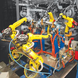
Pre- and postweld vision in a robot cell has significant benefits. For one, it minimizes tooling complexity and cost by eliminating proximity switches for part detection and clamp verification (see Figure 1). It also reduces potential for scrapped parts and verifies model changes, orientation, and part counts in assemblies (see sidebar).
Such systems include software that is either integrated into a third-party system or into the robot controller itself—the latter being a recent advancement that allows all the information from the vision process to pass directly to the robot without third-party drivers or interfaces. Hardware includes a camera, lenses, enclosures, and cables connecting components to the control units.
Cameras, mounted on a separate robot or to a stationary point in the workcell, gather data that can be fed back to the welding robot controller and, if on a network, shared with other welding robots on the plant floor. Consider a row of four robots processing material sequentially. The first cell identifies the part number and model and shares that information with the other robots; as that part is transferred into the next cell, the next robot knows what model it is immediately.
Vision technology can detect and account for variances that previously prohibited parts from being automated. Software with 2-D guidance calculates the relationship between the camera and robot location. When the picture is taken in space, the robot knows exactly where that feature is relative to itself, and it can detect any deviation from the program originally taught. Consider a muffler application. Because the muffler's shape, elliptical halves assembled with end caps, changes ever so slightly from part to part, so does the weld path. A vision system can see the part and gives the robot the information it needs to adjust the weld points accordingly.
Several factors should be considered for vision to work in a robotic welding environment. First, appropriate lighting must highlight the part features that the vision system needs to detect. The cameras produce 2-D gray scale images, so everything is a shade of gray. Dark or shiny surfaces can present problems. Some cameras have an autoexposure feature that gathers more or less light depending on ambient conditions. Others can take multiple pictures to build up an accurate part profile from varying exposures. Thin stainless steel lap joints, with highly reflective surfaces and very small shadows, can require a system like this.
Filters may need to be added to ensure the camera sees certain part features. The filters may be physical, such as a red filter over a camera lens to limit the spectrum of light that the camera sees, which is useful for reflective material like stainless and aluminum. Or they can be software-driven filters that electronically can filter noise in the image, be it arc flash from a nearby welding operation, shadows from a crane moving overhead, or anything else.
Vision technology accurately locates weld seams on objects that otherwise would be welded blindly because of cycle time constraints. In one application, for instance, vision technology was used to verify the X-Y location along with the rotational value of a weld nut (see Figure 2). This application, used at a large power transformer manufacturer, couldn't use touch sensing to gather location data because the surface of the nut actually was flush with the parent material.
As another example, a major OEM of commercial HVAC rooftop units was using vision to locate 2- to 8-foot-long weld seams on lap joints of stainless steel 0.04 to 0.08 inch thick, an application in which tactile sensing would be nearly impossible (see Figure 3).
The heavy-welding sector has struggled to apply automation to variable-width weld joints. But now vision can be used to measure initial conditions for variable-fill applications. It also detects centerline locations of grooves, ensuring the robot provides accurate, consistent, and constant fill. In one construction industry application that had used touch-sensing technology, vision decreased the cycle time needed for gathering weld seam data from 20 seconds to 3 seconds (see Figure 4).
A robot cell identifying a part in space involves a complex equation with several variables. The first variable determines the required resolution. The higher the resolution, the more minute part-position deviations the system will recognize. From that, the equation considers the size of the object itself and the features it needs to detect.
A system can use one camera or multiple cameras, with one farther away from the workpiece to feed rough data to a second camera that's closer. The specific camera setup depends on what's being measured, the workpiece size, cycle time requirements, and the industrial environment.
Apart from other industrial vision applications, welding has unique variables, such as travel speed changes to account for gap variability. A vision system can measure gaps in a joint, and, comparing the image of the actual weld gap with its taught weld schedule, the robot can apply a different weld schedule that's more suitable to account for the new gap size.
Another application might involve a V-groove that, because of unforeseen variability from upstream processes, is larger in some areas and smaller in others. Cameras can view this beforehand and then instruct the robot to choose a weld schedule that will change the volume of necessary weld metal as it progresses down the joint. In this case, travel speed, wire feed, weave, voltage, and other parameters can change to suit, depending on the groove geometry the vision system sees. At the same time, if the joint gap exceeds quality control limits, the part can be rejected—providing an additional layer of errorproofing.
Vision systems do not, of course, change the physics of welding. A robot (or person, for that matter) using a small-diameter welding wire won't be able to weld a 0.40-in.-wide gap, with our without a vision system. Ultimately, though, as long as the weld has a reasonable fit-up, within the specified standards for the job, vision technology can help decipher how best to conquer those fit-up variances.
Vision systems not only allow robots to handle variances in part position and joint geometry, they also allow the robot system to identify different parts within a family or group of parts. Each part geometry does need to be taught to the robot upfront. But once the part programs are in memory and all setup variables are taken into account, a workcell can accept any part in that series. The camera takes a picture of an incoming part; the software identifies it from the list of parts that were previously taught, and then pulls up the associated program. This makes the entire workcell more flexible and efficient, and it can eliminate the need for a human-machine interface (HMI). The operator need not pull up a program from a library of parts, because the robot knows what it's looking for.
This has benefits for assembly as well. Before welding, associated software can draw from this part data and count parts to ensure not only the correct number of parts are ready for welding, but also that all those parts are the right parts and within tolerance.

The Fabricator is North America's leading magazine for the metal forming and fabricating industry. The magazine delivers the news, technical articles, and case histories that enable fabricators to do their jobs more efficiently. The Fabricator has served the industry since 1970.
start your free subscription
Easily access valuable industry resources now with full access to the digital edition of The Fabricator.

Easily access valuable industry resources now with full access to the digital edition of The Welder.

Easily access valuable industry resources now with full access to the digital edition of The Tube and Pipe Journal.

Easily access valuable industry resources now with full access to the digital edition of The Fabricator en Español.
In this episode of The Fabricator Podcast, Caleb Chamberlain, co-founder and CEO of OSH Cut, discusses his company’s...


