


Fighting springback in profound radius bends
The effects of punch and V-die angle interaction
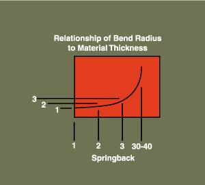 |
| Figure 1: With a profound-radius bend, springback increases dramatically. |
Under normal press brake bending conditions, an inside bend radius that falls between 63 percent of the material thickness and 10 times the material thickness is defined as a radius bend. If the bend radius is less than 63 percent of the material thickness, it is considered a sharp bend. If the bend radius exceeds 10 times the material thickness, it is considered a large-radius orprofound-radius bend.
With a profound-radius bend, springback—the material's attempt to return to its original flat position—increases dramatically (see Figure 1). It is caused by the interaction between the material's compression on the inside of the neutral axis and its expansion along the outside of the neutral axis.
The neutral axis is an area inside the bend, at about 0.44 (44 percent) of the material thickness, where no change in material structure occurs. The neutral axis also is the location of the bend allowance, or K factor—the measured distance along the neutral axis.
V-die Angles
Typically, V-die angles are used to compensate for this large change in springback. V-die angles change with size of the V-die opening. For example:
- For 0- to 0.500-in. (0- to 12.72-mm) V-die openings, the angle is 90 degrees.
- From 0.500 to 1.000 in. (12.72 to 25.4 mm), the angle is 88 degrees.
- From 1.000 to 2.000 in. (25.4 to 50.8 mm), the angle is 85 degrees.
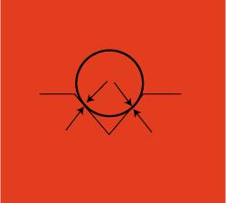 |
| Figure 2: Changing the V-die angle on a standard (unrelieved) die results in interference between the punch and the die and causes coining. |
The reason for this change in the V-die angle is to assist the material around the punch radius, helping to compensate for the increased springback found in larger material thicknesses and larger bend radii.
V dies between 0.500 and 1.000 in. (12.72 and 25.4 mm) are used, for instance, when it is implied that a material thickness or inside bend radius is appropriate for that width—for example, a one-to-one relationship between the material thickness and inside bend radius—and that a certain amount of springback will be encountered.
A perfect V-die angle can be determined using this formula: Bend angle - Springback = Optimum V-die angle
For example: 90-degree angle - 13-degree springback = 77-degree die angle
Except for custom-made tools, however, fabricators still are limited to the V-die angles of 90, 88, 85, 78, etc., in off-the-shelf dies. In fact, some older V dies are produced with only a 90-degree option.
While this 90-degree tool angle does nothing to compensate for springback, it does have an important advantage: When the punch radius is produced using round stock, the punch angle is 90 degrees, matching the V-die angle and thus preventing interference between the punch angle and the V-die angle (see Figure 2).
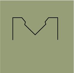 |
| Figure 3: One solution to prevent the production of flats on both sides of the punch body is to use a relieved die. |
Relieved Dies
When the V-die angle is changed on a standard (unrelieved) die, the result is interference between the punch and the die, causing coining to take place on both sides of the punch and die (see Figure 2). If coining is allowed to occur on a profound-radius bend, flats will be produced on both sides of the punch body from overtonnage of the tools and the workpiece.
One solution to this situation is to use a relieved die (see Figure 3). This style of V die removes all interaction between the punch and the die, regardless of the angle. When the die is relieved, the punch passes freely into the V-die body, taking advantage of the V-die angle in compensating for springback.
Neither a relieved nor unrelieved V die will reproduce the radius of the punch without having some kind of urethane backup in the die space before the forming process. This backup generally is a V-shaped pad of urethane that interacts with the material and the punch.
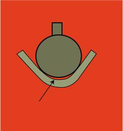 |
| Figure 4: A leading radius formed in advance of the punch is smaller than the punch radius and is defined as multibreakage. |
Without this backup, a leading radius is formed in advance of the punch (see Figure 4). This leading radius is smaller than the punch radius and is defined as multibreakage. Multibreakage always is present, but it is a predictable value that can be calculated using the following formula:
Multibreakage (Ir) = Rp - [Rp x {(Rp x 1.5) + 0.030} - Mt]
Where: Rp = Punch radius
- Ir = Achieved inside radius
- Mt = Material thickness
Adjusting the punch radius allows the fabricator to achieve the inside radius desired in the final product.
Multibreakage occurs in all bends; however, in smaller-radius bends or those in which coining or bottom bending is employed, the multibreakage is so small or nonexistent that it is not a factor in the forming process. For profound-radius bends or those that have clearly visible multibreakage, some form of compensation is necessary, either by urethane backup or calculation of a new punch radiusthat is capable of producing the desired inside bend radius.
About the Author

About the Publication
subscribe now

The Fabricator is North America's leading magazine for the metal forming and fabricating industry. The magazine delivers the news, technical articles, and case histories that enable fabricators to do their jobs more efficiently. The Fabricator has served the industry since 1970.
start your free subscription- Stay connected from anywhere

Easily access valuable industry resources now with full access to the digital edition of The Fabricator.

Easily access valuable industry resources now with full access to the digital edition of The Welder.

Easily access valuable industry resources now with full access to the digital edition of The Tube and Pipe Journal.

Easily access valuable industry resources now with full access to the digital edition of The Fabricator en Español.
- Podcasting

In this episode of The Fabricator Podcast, Caleb Chamberlain, co-founder and CEO of OSH Cut, discusses his company’s...
- Trending Articles
1
AI, machine learning, and the future of metal fabrication

2
Employee ownership: The best way to ensure engagement

3
Dynamic Metal blossoms with each passing year

4
Steel industry reacts to Nucor’s new weekly published HRC price

5
Metal fabrication management: A guide for new supervisors
