Get your schedule in order
How first- and second-order decisions affect resistance weld schedules
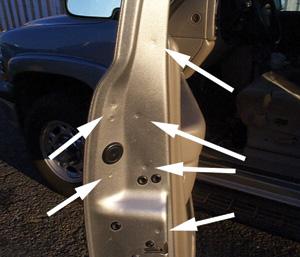 |
| Spot welds in this galvanized steel truck door frame must be free of surface burrs that can tear clothing when someone enters or exits the vehicle. High weld strength also is necessary for door assembly support when the vehicle is in service, especially in the event of a crash. These service characteristics depend on the weld schedule. |
Service quality of products with resistance welds can vary considerably, depending on whether the resistance welding machines are operated with optimal weld schedule settings or with untested, best-guess settings.
Resistance welding is one of the most frequently used processes to make products we use every day. Some of them are:
- Automotive body and suspension components
- Aircraft seats
- Turbine engine components used in aircraft and power generators
- Sheet metal enclosures, such as computer housings
- Sheet metal office furniture and appliance components
The quality of the resistance-welded components depends on the weld schedule. Weld schedules comprise several machine settings: weld current, time, and electrode force are common settings for spot, projection, and seam welding.
Many resistance welding machine and electrode suppliers offer standard weld schedules for common metal combinations.
Unfortunately, more than half of the metal combinations welded today involve special metals or joint configurations. One common example is joining thick metal to thin metal. In addition, coatings are added to one or both metals in a weld joint for rust protection, such as in galvanized metal.
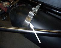 | 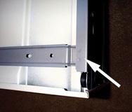 |
| Three resistance welds hold together this stainless steel banding clamp. The clamp holds a 10-pound Halon fire bottle on the front end of a 200-MPH drag racing car. Strength resulting from a well-developed weld schedule is needed in this case. | Two spot welds hold the corner of a frame, shown in a bottom view of this filing cabinet drawer. This frame must be free of surface burrs so it won't cut the user. The component also must have high strength to support a full load of office files. |
The increased use of weld-through sealants and adhesives for corrosion protection, strength, and sound deadening also makes resistance welding more challenging. With aluminum, manufacturers more often are demanding low-cost sheet metal without special added surface treatments for optimal welding. For example, General Motors' Suburban® lift gate is made from aluminum without surface pretreatment for welding. Similar assemblies often involve welding through sealants.
These types of complicated applications require special weld schedules that aren't always obvious or easy to set by trial and error.
First-order Decisions
In a machine shop, machinists simply make a hole bigger if it's not big enough. This is known as a first-order decision. It involves a single change.
In some cases in a resistance welding shop, first-order decisions apply. For example, a known weld setup for one application, such as thin metal, will make undersized welds in a new metal combination, such as thicker metal. Sometimes you can make one adjustment—increase the weld current—to address the situation. This also is a first-order decision.
Second-order Decisions
Unfortunately, resistance welding usually isn't that simple. For example, 1-millimeter-thick metal is common in automotive, appliance, and job shop manufacturing. Resistance spot or seam welding 1-mm bare steel to 1-mm bare steel sheet metal typically requires about 8,000 amps, 10 cycles of weld time, and 500 pounds of weld gun force.
However, welding the same thicknesses but with a galvanized coating requires changes to all three settings. A weld schedule of about 12,000 amps, 16 weld cycles, and 700 lbs. of weld gun force is typical. Although settings for both setups now are common, it wasn't that simple a short time ago.
At one time the automotive industry had to move rapidly from uncoated steel to galvanized steel across an entire product line. Changing only one weld setting, such as current, didn't work. Welding wasn't reliable, the weld schedule needs weren't common knowledge, and weld schedules had to be developed.
The move from uncoated to coated metal required second-order decisions to change several settings. Changes to all three settings were successful in most cases. In addition, other improvements—investing in more robust machinery and plant welding power to handle the increased current, time, and force—were necessary.
But second-order decisions often aren't as obvious as first-order decisions. Add to that the other changes that are often necessary, and the task can be difficult.
Weld Schedules for the Short Term
Many weld schedules are suitable for short-term use. Many resistance welding setup professionals use best-guess weld schedule settings to improve welding. They steer toward first-order changes, and their machines often make good production welds in the short term.
However, many times the schedules aren't good for long-term use. For example, when long-term effects such as machine mechanical wear, dirty metal, common machine fluctuations, and utility changes occur and the weld schedule isn't well-developed, problems can arise, including strength variation, stuck (breaking) welds, and poor cosmetic appearance.
One way to prevent this is by determining process windows combined into a weld lobe.
 |  |
| Figure 1 This process window for weld current shows the results of various welds tested with different current settings. | Figure 2 Setup parts can be made for another setting, such as weld time. Again, the results can be plotted in a process window to reveal the range of good welding. |
Process Window: The Basics
A process window is the range of adjustment for a weld setting between the upper and lower limits. A weld current setting that results in a small weld size establishes the lower limit, for example. A higher current setting at which expulsion or electrode sticking occurs establishes the upper limit.
Testing various weld samples made with different settings can reveal the process window. If you pull the test parts apart, you can examine the weld size or strength. If the weld is small, good, or expelled, the results can be used to plot a chart (see Figure 1). You can perform the same test for weld time (see Figure 2).
Weld Lobe
When you plot the testing results in this manner, you can determine the lobe of good weldability. Welding in the good range of settings (shown inFigure 3within the solid boundary) will produce good welds.
 |  |
| Figure 3 These results are plotted to show the lobe of good weldability. Welding in the good range of settings—within the solid boundary—will produce good welds. | Figure 4 Two lobe boundaries can exist—good and marginal. The area between the boundaries is a mix of good, marginal, and bad welds. |
In addition, two lobe boundaries can exist (see Figure 4). The inside boundary defines a lobe of all good welds. The outside boundary is a marginal boundary. The area between the boundaries is a mix of good, marginal, and bad welds. This is an important reason to select settings that stay toward the center of the lobe or inside boundary and away from boundaries where the welds could be marginal.
In this case, weld current of about 8.8 kiloamps (kA) and weld time of 11 cycles is optimal.
Setup parts can be made with different combinations of current and time settings. You can test them, plot the results in two process windows, and combine them to make a weld lobe. Weld lobes can be created for any combination of settings, such as current and gun force.
Want more information? If you want to know how Ford Motor Company's New Model Product Development Center (NMPDC) in Allen Park, Mich., uses resistance welding to reduce costs and improve quality, read "Revving up weld quality." |
Bob Szabo, author of Resistance Weld Schedule Development and Resistance Welding Safety for Operators, can be reached at Szabo Publishing, P.O. Box 571, Elmira, CA 95625, 707-446-2917, fax 707-446-6897, bob@szabopublishing.com, www.szabopublishing.com.
About the Author
About the Publication
subscribe now

The Welder, formerly known as Practical Welding Today, is a showcase of the real people who make the products we use and work with every day. This magazine has served the welding community in North America well for more than 20 years.
start your free subscription- Stay connected from anywhere

Easily access valuable industry resources now with full access to the digital edition of The Fabricator.

Easily access valuable industry resources now with full access to the digital edition of The Welder.

Easily access valuable industry resources now with full access to the digital edition of The Tube and Pipe Journal.

Easily access valuable industry resources now with full access to the digital edition of The Fabricator en Español.
- Podcasting

In this episode of The Fabricator Podcast, Caleb Chamberlain, co-founder and CEO of OSH Cut, discusses his company’s...
- Trending Articles
1
Sheffield Forgemasters makes global leap in welding technology

2
Welding student from Utah to represent the U.S. at WorldSkills 2024

3
Lincoln Electric announces executive appointments

4
Lincoln Electric acquires RedViking

5
Engine-driven welding machines include integrated air compressors