Contributing Writer
 |
To cut stainless steels and other metals with plasma successfully, fabricators need the following tools:
During the plasma cutting process, material is in the molten state inside the kerf zone. Mechanical problems such as motion irregularities cause vibrations, which transfer through the machine axis into the cut edge. These vibrations are solidified into the cut surface and can be easily mistaken for process problems. These motion irregularities and/or vibrations cause a rough-cut surface, nonlinear cut edges, and overall poor cut quality.
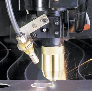
To initiate the cutting process, a pneumatic probe locates the material position and provides an accurate and repeatable pierce height. After the pierce is made, the plasma arc cutting (PAC) voltage from the plasma power unit is used in a closed-loop process control system to maintain torch-to-material height while cutting.
Automatic voltage control precisely maintains the torch tip-to-material distance. This is vital when processing thin sheet and stainless steel plate.
Fabricators can process stainless steel with clean-cut surfaces by using nitrogen or a blend of oxygen and nitrogen as a plasma gas. These plasma gases provide a nonoxidizing plasma arc, which produces a clean-cut edge that is weld-ready without secondary operations.
Nitrogen also increases electrode life by preventing oxide formation on the tip of the halfnium electrode. Halfnium is used as the metallic element in the electrode, which also is compatible with oxygen as a plasma gas for steel cutting.
Pure oxygen is not recommended as a plasma gas for stainless steel cutting because of its oxidizing characteristics, which leave an oxidized, contaminated cut edge.
Compressed air is not used for cutting because it often is contaminated with water, oil, or other contaminants. These contaminants can cause regulator and solenoid valve breakdown, as well as plasma double-arcing.
The type of stainless steel assist gas (or shield gas) to use varies according to the material thickness and the desired cleanliness of the cut edge. Based on each assist gas type and the material thickness, different conditions and chemical reactions result.
The five main assist gases are:
The assist gas serves several purposes:
| Assist Gas Type | Material Thickness (In.) | Condition |
|---|---|---|
| Clean, dry compressed air | 0.028 – 0.125 | 19 percent of the oxidizing gas flushes the kerf, leaving a gold-bronze-colored edge. |
| Carbon dioxide | 0.125 – 0.500 | A low-flow-rate carbonizing reaction provides a slag-free, brown-colored edge. |
| Nitrogen plus hydrogen | 0.500 and thicker | This combination produces a reducing atmosphere, a bluish color, and a more stable premix gas with no balancing of the two gasses. |
| Nitrogen plus liquefied petroleum | 0.187 – 0.500 | This combination produces a reducing atmosphere, breaking down propane into carbon and hydrogen. In increases cutting speed and piercing capacity, and leaves a nickel-colored edge. |
| Pure nitrogen | 0.028 – 0.078 | Inert gas flushes the kerf and evacuates it for a clean, chromelike edge with a minimum heat-affected zone. A high flow rate of assist gas also cools the process, resulting in less part distortion. |
| Figure 1. The assist gas and material thickness influence the cutting conditions and chemical reactions. | ||
Advanced piercing controls used in clean-cutting stainless steel sheet and plate include:
As the material thickness increases, higher pierce heights are necessary to prevent shield cap and nozzle damage. This is achieved by using higher pilot current to connect the pilot arc to the workpiece. If pilot currents are set too high, however, premature nozzle or electrode failure can occur if the pilot arc current burns the nozzle.
Polyethylene-coated stainless steel sheet is used extensively in industries such as food service. The poly film is applied to the material after the polishing process. The film, usually 3 mils thick, is used to protect the polished stainless steel finish. Cutting this material without burning and melting the polyethylene film requires the use of nitrogen assist gas.
The nitrogen assist gas flushes the slag away from the kerf. It also shields the cutting zone from oxygen, preventing burning of the polyethylene film.
The polyethylene coating must adhere well enough to withstand the strong blowing force of the assist gas. The adhesion strength of the polyethylene coating must be at least 11 ounces pull strength per square inch, or the force of the assist gas will cause the film to lift, allowing a nitrogen air pocket to form and causing torch collision. If the gas pocket trapped beneath the poly film is more than 0.030 inch, it will catch the torch, causing cut process failure. The material should be placed on the machine cutting table with the coated side facing up. If it is not, the positive part of the circuit cannot be completed.
Many variables are important to consider when using the PAC process to clean-cut stainless steel sheet or plate. Fabricators must scrutinize many machine and process possibilities, no matter the sheet or plate thickness.
Stephen St. Hilaire is Senior Process Engineer for Komatsu Cutting Technologies Division, 265 Ballardvale St., Wilmington, Massachusetts 01887, phone 978-658-1650, fax 978-658-1655, e-mail steves@fineplasma.com, Web site www.fineplasma.com. Komatsu Cutting Technologies Division, a wholly owned subsidiary of Komatsu America Industries LLC, designs, manufactures, and services RASOR™ Fine Plasma systems for plate cutting.


The Welder, formerly known as Practical Welding Today, is a showcase of the real people who make the products we use and work with every day. This magazine has served the welding community in North America well for more than 20 years.
start your free subscription
Easily access valuable industry resources now with full access to the digital edition of The Fabricator.

Easily access valuable industry resources now with full access to the digital edition of The Welder.

Easily access valuable industry resources now with full access to the digital edition of The Tube and Pipe Journal.

Easily access valuable industry resources now with full access to the digital edition of The Fabricator en Español.
In this episode of The Fabricator Podcast, Caleb Chamberlain, co-founder and CEO of OSH Cut, discusses his company’s...