


Transfer Press Simulation Engineer
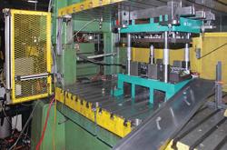
Photo taken by the author at KB Stamping, Belmont, Mich., 616-866-5917. Used with permission.
In stamping die manufacturing, cost is the No 1. factor in determining where work is placed. It doesn’t matter if the work is die design, die build, or production stamping; in the end it usually comes down to cost. Yes, being on time and producing a quality product are important. In fact, they are requirements; otherwise, your company would not be considered as a potential supplier in the first place. But cost still is the deciding factor.
So what can you do to reduce costs and improve the bottom line?
Die design ideas can dramatically reduce cost during the build and production stages. The reality is that the die designer’s choices greatly affect the tool’s lifelong profitability.
Designers should follow design-for-manufacturability guidelines when designing stamping dies, such as using as few components as possible; making components easy to machine; using off-the-shelf standard components; and making the tool simple to assemble and disassemble.
Designers need to know the cost of die components. This will help them choose between two methods that produce the same result. For instance, consider guiding and retaining a pad. Standards often allow different ways to do this, and one way may be less expensive. Designers may integrate pins, bushings, and keepers, and each may be dedicated to either guiding or retention. But if one product can accomplish both guiding and retaining simultaneously, designers should consider it (see Figures 1 and 2).
If designers know the costs of components and the machining required, they can work to reduce the cost of building the die while they design it. For instance, a stripper pad may work equally well with four medium-sized nitrogen cylinders or eight small cylinders. Both arrangements provide the needed pressure in the right areas.
But in many cases, the four medium-sized cylinders cost less. The price for the four is less than for the set of eight, and the four cylinders also require (depending on the tool) roughly 25 percent less machining time. To make these larger pockets, the mill also can use a larger-diameter cutter, which has a high metal-removal rate.
Designers also should take into account the cost of tool steel. For example, a company may request all form steels to be made from D2 grade steel and won’t consider using 4140 as an alternative that costs less. Hardening 4140 also is less expensive than hardening D2. True, 4140 may not work for forming high-strength materials, like those used for door beams or roof pillars, but for stamping cold-rolled steel parts in shorter production runs, less expensive tool steel just makes sense.
Dies should be designed to last just beyond their expected production life. Don’t lose profits by overdesigning and overbuilding dies. If expected production is 50,000 parts, do not design and build a die that will last for 500,000 parts. Use vendor engineering data to confirm that the tool steels and purchased components will last the expected life of the tool.
Don’t be afraid to ask for part changes and concessions that can simplify the die, reduce stock usage, increase part quality, and improve die conditions. If your chain of communication with customers is efficient, you will get feedback on your requested changes quickly. Asking for such part changes and concessions can reduce the total die cost throughout design, build, and production.
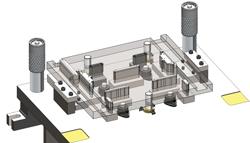
Figure 1: This die, which uses a number of pins, bushings, keepers, and a large pad, requires significant machining.
Also, use the latest software and hardware. Why design in 2-D and then model up details in 3-D for after-process machining? Available 3-D design software is fast, accurate, and affordable. Some versions automatically generate machining tool paths, create 2-D design and detail prints, and even provide real-time component cost to the designer.
Adopt new build practices that reduce waste. Recognize that continuous improvement requires change on everyone’s part. This includes every step of the build process, from when raw steel and purchased components are received, all the way through press tryout.
Consider using new products and services, and propose these items to your customer (that is, people in production). Request demos, samples, and engineering data from vendors. Ask who uses the product or service, whether there are any reported failures or recommended uses, and what the cost savings are now and over the life of the tool.
Look at areas to reduce machining costs. These include using the latest techniques, cutters, tool path software, and workholding equipment. Remember, demos are free. Be open to alternative processes and the latest technology in all areas of machining.
Improve channels of communication with design and production. Maintain positive attitudes, be open-minded, and recognize everyone has the same goal and plays on the same team. For continuous improvement to be effective, you must maintain respect and professionalism for all individuals involved regardless of their position.
All this fosters an environment of shared knowledge and a healthy questioning of the status quo. Just because you’ve been doing it the same way for 20 years doesn’t mean it’s the best way.
For instance, consider graphite-impregnated wear plates. Many are more familiar with long-lasting plates made out of a soft material like bronze that work in concert with the plate’s lubricating graphite buttons. But if that wear plate lasts only 15,000 hits, what went wrong?
In this case, the cause may be excess load factors, especially if available space limits the wear plate size. The small plate size and high load factors may make a graphite-impregnated steel wear plate a better choice. If designers, production, and die-build personnel had open communication from the get-go, this problem may have been avoided.
As another example, one company requires trim steels with possible risk of one-way thrust to have a key behind them, or requires such steels to be heeled. It requires this for every tool, even if the die is trimming cold-rolled stock only 0.030 inch thick. Another company trimming the same stock uses a die with no keys or heels, and just relies on adequately sized screws and dowels to hold the steels in place.
Which company is right? It depends, and regardless, it’s not a matter of who’s right or wrong. Both may be following what they perceive to be the best practices for the application; or one may be overdesigning a tool and wasting money; or one may be underdesigning a tool and (again) wasting money because of premature failures in production. There is no way to really know without documentation of past experience. The point is, those best practices should be backed up with documentation, not just tribal knowledge.
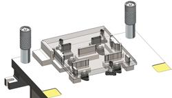
Figure 2: This die has fewer components, requires less machining, and is less expensive to make than the design in Figure 1.
Some companies take pictures and record data for every die failure. Employees analyze the problem, identify its root cause, and use that knowledge when building another die for a similar part. Instead of relying on a project manager’s memory or a “this-is-the-way-we’ve-always-done-it” standard, these companies have records and written reports that say why a die failed and how to avoid it in the future. This information then must be shared, either directly or through updated die standards, with everyone involved in design, build, and production.
Up to this point design and build have plowed, planted, watered, and grown the crop. Now it’s time to harvest it with production stamping.
Over the life of the tool, production personnel should keep accurate records of maintenance, failures, or mishaps involving the die. As mentioned earlier, accurate failure analysis is so important for continuous improvement to be effective. When updating build standards or design requirements, make certain actions outside of the designer’s and builder’s realm do not affect continuous improvement feedback. These variables can include improper die setting, mishandled dies, poor die maintenance, and poor press maintenance.
For instance, consider a die damaged by a die setter who failed to align the tool properly using the press locating keys. A company might try to “engineer out” the problem by adding specialized cone locators to all future dies. Yes, this can improve die location, but the strategy also may require the machine shop to mill custom cone-ring locator elements. This effectively adds a few hundred dollars to the cost of each tool. Depending on the application, it may also increase die setup time in the press.
Why go through the trouble when, in the hands of a trained die setter, less expensive keys would suffice? In this case, spending a little time to train employees properly can go a long way. Do not go overboard and require more die components or more machining to make up for a problem that could be overcome with proper training.
Production personnel also must be open-minded to new components and techniques that lower the cost of the die build. Use available vendor engineering data to reduce the risk of negative effects on initial production stamping. Ask if other stampers are using these new components and techniques, and find out what benefits or drawbacks resulted.
Design, build, and production teams should investigate what other successful suppliers are doing to reduce their costs. It might sound a little like cheating off somebody else’s high school math test, but it is not. Think back to what prompted you to buy that first CNC mill, wire EDM, or 3-D CAD software. You probably took the step because of the reported success from your competitors.
Don’t let personal pride keep you from trying new services or products that reduce die cost. Let your company benefit from innovations by using them to your advantage.
Sometimes personnel design certain elements of a die to add adjustability, improve quality, and reduce unplanned maintenance. But when doing so, it helps to see the forest for the trees. Improving a tool in one way can make it perform worse in others.
Consider nitrogen cylinders. Plumbing together nitrogen cylinders and connecting them all to one pressure control panel may sound like a good idea in some situations. During production an operator can monitor the form-pad cylinders and, should a slow leak occur, top the plumbed cylinders off to the required pressure.
Here’s the problem. Off-the-shelf, a nitrogen cylinder can leak in only two places: the fill port and the rod seal. So if a die has 10 nitrogen cylinders, it has 20 possible leak spots. But if you plumb all of the cylinders together, you effectively triple the number of leak opportunities because of all the fittings and hose connections.
It is rare for a nitrogen cylinder to fail prematurely in typical applications, but it can happen, of course, especially in harsh, abrasive environments where particulate in the air wears the cylinder rods. Or perhaps the cylinder’s pocket may not have been machined dead-flat, forcing the cylinder to sit at a slight angle (which, in any case, is a machining problem, not a nitrogen cylinder problem).
But in many cases, plumbing nitrogen cylinders can actually reduce their reliability and add to maintenance requirements. Many cylinder-makers guarantee their product to last a million strokes. Sometimes it may be better to go with a less expensive alternative and trust the cylinder manufacturer’s million-stroke guarantee, rather than plumbing cylinders together and adding all those potential leak spots.


The Fabricator is North America's leading magazine for the metal forming and fabricating industry. The magazine delivers the news, technical articles, and case histories that enable fabricators to do their jobs more efficiently. The Fabricator has served the industry since 1970.
start your free subscription
Easily access valuable industry resources now with full access to the digital edition of The Fabricator.

Easily access valuable industry resources now with full access to the digital edition of The Welder.

Easily access valuable industry resources now with full access to the digital edition of The Tube and Pipe Journal.

Easily access valuable industry resources now with full access to the digital edition of The Fabricator en Español.
In this episode of The Fabricator Podcast, Caleb Chamberlain, co-founder and CEO of OSH Cut, discusses his company’s...


