


Robotic Welding And Laser Cutting Specialist
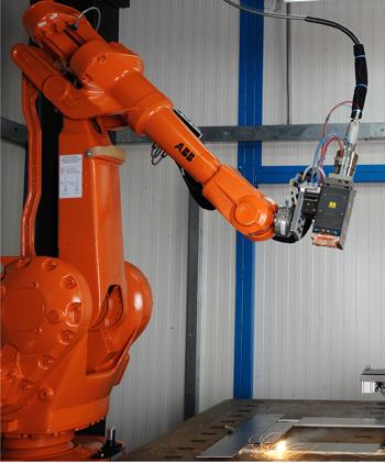
Figure 1: Robotic welding, such as this remote laser welding application, requires the articulating arm to make accurate movements. Not only do the start and end points matter, but so does every point in between.
When it comes to flexibility, nothing beats the human arm. Need to reach for a cup of coffee behind your computer monitor? No problem. You extend your arm up and over, carefully grasp the cup, lift it over, and enjoy. There’s a problem here, though. You need to grasp it carefully. One wrong move, and you’ll spill coffee over the table.
Why do you have to be careful? Because, from a purely mechanical perspective, your arm has a big job to perform. To reach over the monitor, your arm articulates on several axes, back and forth and rotationally, and it must lift and maneuver over the monitor with just the right amount of force, at just the right trajectory and speed so as not to spill a drop. And when it comes to speed, it’s the acceleration and deceleration that really count. Lift the cup or jerk en route (accelerate) too quickly, and the coffee splashes all over. Slam the coffee cup down on the desk (decelerate too quickly), and you still slosh coffee everywhere.
To avoid all this, let’s say, for whatever reason, you want to develop a machine to lift the coffee cup for you. The simplest and most accurate way to do this would be to build a machine that runs on vertical and horizontal tracks—linear axes. You then have an end effector that’s designed to lift the coffee cup the same way every time. In this situation, the device moves precisely and consistently. Your arm cannot reach over the monitor precisely the same way every time, but your new contraption, with its linear axes, certainly can.
But now say you buy a new desk, and you don’t need to reach for coffee anymore. What are you going to do with this contraption you built? Not much.
This illustrates the traditional trade-offs manufacturers have had to deal with in machine automation. Say you needed a machine to move from one point to another. If you cared only about accurate positioning at the end points—like in a pick-and-place material handling operation—you used an articulating-arm robot. If you needed absolute precision on the path between those end points, you would turn to a system with linear axes. Compared to a robot arm, such systems can’t reach into every nook and cranny within a work envelope, nor can they be retooled easily for a different application. But thanks to those linear axes, they’re precise.
But what if an arm could compensate for its positioning errors? In recent years robotics technologies have narrowed the trade-off gap. This gap has narrowed in part because of advanced techniques used to make the robot arms themselves. At the same time, integrated software has helped make the robot arm more intelligent.
Consider robotic welding (see Figure 1). For decades articulating-arm robots have wielded resistance spot welding electrodes that pinch the metal and perform a weld. The path between each spot weld needs to be consistent, but it doesn’t need to be absolutely accurate. If the robot’s position, speed, acceleration, or deceleration varies a little bit between welds, no one really cares. It has to be accurate enough to avoid obstructions, but that’s about it. It’s the position of the spot weld that really matters.
Now consider wire welding along a straight or even contoured seam. In this case, we really care about exactly where that robot path is between the start and end points, and we also care about the speed, acceleration, and deceleration along the joint. But this is wire welding, so the joint does have some gap tolerances. It can handle a little bit of variability. For years robots have been accurate enough to handle the process, and they’ve been more cost-effective too. Not only have prices for robot arms dropped precipitously over the years, they are flexible (more reach within the work envelope) and can be retooled easily for another application.
What about laser welding? This process often requires extremely high precision and accuracy, depending on the joint geometry. That’s why sometimes people choose to use a prismatic system, one with linear drives. But today more robots are being used even for these kinds of precision applications.
Technically speaking, every physical positioning system has errors. The track on a linear system is machined to a precise tolerance, but there still is a tolerance plus or minus some amount (usually with a lot of zeros to the right of the decimal point). The drives that send the processing head along the track also have slight positional errors. It’s just the nature of anything manufactured. No matter how precise the manufacturing method, nothing is absolutely, perfectly accurate.
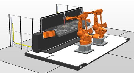
Figure 2: These robots have parallel linkages that minimize vibration without adding mass to the rest of the system.
What really makes a linear system so accurate isn’t the fact that it lacks positioning errors, because, again, nothing is perfect. It’s the fact that the errors don’t compound or stack up. An error in one axis doesn’t affect the errors in the other axes.
In a typical 5-axis prismatic system, each axis is linear except for the last two, which are rotational. A processing head can move to a certain point on the X and Y plane that may be just a hair off, but that inaccuracy won’t affect the head’s ability to move down to the workpiece in the Z direction. The XY error still is there, but it has no practical effect on the Z position, at least in most applications sheet metal fabricators deal with. The last two rotational axes do compound, but this occurs right at the workpiece, so the compounded error doesn’t add up to very much at all.
An articulating arm doesn’t operate this way. On a 6-axis robot, the error of each axis contributes to the overall positioning error of the arm. A minute error in the first axis, near the base, compounds with all the errors of the remaining five axes. By the time it reaches the sixth axis at the end effector, that error can be significant.
And, again, anything manufactured has a tolerance too, and this includes every link in a robot arm. If one joint’s radial position is off a few arc-seconds, and the attached link is a little longer or shorter than nominal, that will magnify the error. So the machining tolerances of the links play a role, as does the location of the joint within the link.
Another error is deflection of the arm; that is, the bending of the arm during acceleration and deceleration. And then there’s an error called compliance, which deals with gearboxes giving a little bit, also most prominent when changing speed.
On a midsized robot, all these factors historically have created an average positioning error of ±5 mm at the end of the robot arm. But advancements in recent years compensate for these errors, which is why precision processes, like laser welding, can be performed well with an articulating arm. Now, average error on a robot with absolute accuracy can be as small as ±0.5 mm.
Some robot link components today are manufactured with a laser tracker, which measures the position of the arm at specific joint locations. The robot is given the axis position and moves to that point in space. The laser tracker records the actual position and compares that to the one that was programmed.
This is done well more than 100 times, measuring points throughout the work envelope, with the robot working at its maximum payload. This procedure—comparing the difference between the actual and programmed position—helps construct an algorithm that produces the offsets, which account for positioning errors and make the entire robotic system much more accurate.
Of course, when integrating any precision robotic application, you also need to consider factors external to the actual robot arm. For example, the robot payload—like the laser processing head—should not exceed half the maximum payload amount. A laser head that’s 7 or 8 kg should be put on a robot arm that can handle twice that amount, or at least 16 kg.
The payload measurement reveals the maximum weight the robot can move. The accuracy is in the static position—at the start and end points—which is all that really matters in most material handling applications. But at or near payload, the positioning accuracy between those start and end points suffers.
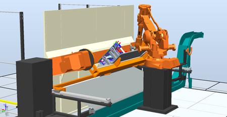
Figure 3: CAD systems tailored for the robot can develop and simulate programs to ensure process consistency, adjusting speed and laser power for the application at hand.
Think about picking up a sturdy pen with a large boulder attached to it, and try drawing a circle with it. You could physically move it in a circle, and start and end at the same place, but the circle wouldn’t look good at all. Now remove the rock, and you just have a sturdy pen remaining. The weight of the pen makes it easy for you to press it against the paper and move it to produce a good-looking circle. Replace it with a really lightweight pencil, and you find that it’s so light that it just doesn’t fit well in your hands, so again, the circle isn’t as good-looking.
The same thinking applies to robotic payloads for precision applications. When thinking about payloads—processing heads, cables, hoses, and the like—you need to aim for a happy medium, not too heavy and not too light. This includes upper arm load, or attached load, such as dress packs and other auxiliary equipment. When possible, reduce or eliminate as much attached load as you can.
A robot’s concrete foundation also plays a role here. These days more robots are being integrated as part of palletized cells, units that can be disconnected and moved with a fork truck to other areas of the plant. This can make automation truly flexible, but you still need to account for the physical attributes of a robotic system, including its need for a good foundation. Industry standards, like those from the Robotic Industries Association, address this.
A robot’s mass is much less than that of a linear-axis system, so the foundation requirements aren’t as stringent, but robots still need to be able to transfer enough energy into the floor to absorb vibration. If the concrete can’t absorb that energy, it will oscillate back up into the robot arm.
Certain palletized systems work very well for precision applications, but they can do this in part because they effectively transfer kinetic energy into the floor. Conversely, palletized systems that don’t effectively transfer this energy may work for some material handling applications (with additional setting time), but not one involving precision movement.
A robot may be connected to the foundation but still encounter problems if it’s too close to another machine that’s creating its own vibrations. Some get around this problem by pouring a concrete isolation or vibration-dampening pad, which keeps out externally generated vibrations. But in this case, it is especially important to direct the robot’s kinetic energy through the pad and into the ground. If the robot isn’t grounded properly, the isolation pad will trap the vibrations the moving robot produces, which then have nowhere to go but back up into the robot arm.
A robot arm must have a certain amount of stiffness to move without vibration. To achieve that stiffness, robot arms for precision applications may need to be built with extra mass, which can absorb some of that energy and minimize this vibration.
A parallel-arm robot, with two parallel linkages near the base, aims to achieve the same thing, without the need to add mass to the rest of the system (see Figure 2). This helps the robot keep steady at the far reaches of its work envelope. This also makes it ideally suited for precise applications like laser welding.
Manufactured to absolute accuracy, and external variables like payload and vibration accounted for, a robot now is ready to perform a precision operation. But there’s one more element: software.
Velocity, acceleration, and deceleration all can affect the characteristics of precision processes like laser welding. Today many run simulations not just to ensure the application can access the workpiece where needed and avoid obstructions, but also perform the actual process to the level of accuracy required.
Say a laser cutting application has the robot maneuvering around a corner. This requires the robot to decelerate and accelerate, but how will these speed changes affect cut quality? In laser processing, slowing down gives more time for heat to build up.
CAD systems tailored for specific robots integrate closely and, hence, can help ensure path accuracy and process consistency (see Figure 3). If the solid model shows that the robot will need to cut around a tight corner, the software will slow the robot down as needed. An offline robot programming system then can take this information and write a program that will instruct the robot to reduce laser power in-process, while it moves around the corner, to maintain cut quality throughout the contour.
Decades ago buying a robot required a hefty financial commitment. It was for the specialized application, like high-volume pick-and-place, in which the savings far outweighed the high price tag. That scenario has changed entirely. Many now may initially consider a robot for an application because it’s much less expensive than alternatives.
As always, the choice depends on the application. If you’re cutting hole after hole on flat surface after flat surface, a linear-drive system probably is your best choice. But if you’re cutting various products, and perhaps retooling your automation for another job down the road, a robot may well suit your situation.

The Fabricator is North America's leading magazine for the metal forming and fabricating industry. The magazine delivers the news, technical articles, and case histories that enable fabricators to do their jobs more efficiently. The Fabricator has served the industry since 1970.
start your free subscription
Easily access valuable industry resources now with full access to the digital edition of The Fabricator.

Easily access valuable industry resources now with full access to the digital edition of The Welder.

Easily access valuable industry resources now with full access to the digital edition of The Tube and Pipe Journal.

Easily access valuable industry resources now with full access to the digital edition of The Fabricator en Español.
In this episode of The Fabricator Podcast, Caleb Chamberlain, co-founder and CEO of OSH Cut, discusses his company’s...


