


Making your own punch and dies
Speaking from 30 years of experience, I'd say this situation probably is a fact of life for 99 percent of us. Whether we are doing some in-house engineering and design or working at the press brake, the thought is the same.
An End to the Dilemma
Sure enough, there is a reasonable solution to this problem, and it's not necessarily to buy a new tool. Assuming that you have or at least have access to a laser, you can produce the required tool to specification relatively easily.
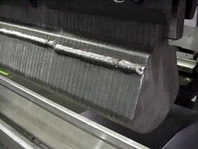 |
| Figure 1 |
The tool shown in Figure 1 was produced by cutting multiple tool sections from 1/4-in.- (8-mm-) thick material. The type of material used to create the tool should be based on the material the tool will form. Hot-rolled, pickled, and oiled (HRPO) steel is the most common material for tools because it is suitable for most forming applications.
Making the tool is a simple process, but first you must consider some very important design factors.
Punch
Before deciding the punch body profile, you must consider the mounting tongue. If you are producing a tool similar to the one shown in Figure 2, which has spacing between the different punch sections, instead of a solid die like the one in Figure 1, you must make sure that there is sufficient contact area between the punch and ram. With not enough contact area, the punch tongue can become embedded in the ram and cause spot damage to the press brake.
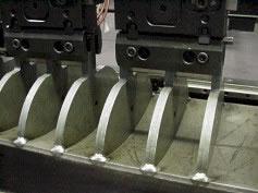 |
| Figure 2 |
The tool shown in Figure 2 was designed with spacing to reduce its overall weight. Although this tool had reduced weight, under a heavy load, it could have caused some serious spot damage to the press brake because there wasn't enough contact area.
The second consideration that is no less important than tongue size is the punch angle of the tool, for example, 90, 88, 87 degrees complementary. It's imperative that the complementary angle of the punch be equal to or less than the included angle of the V die. Failure to achieve this ratio will cause myriad f problems, such as exploding the V die or damaging the workpiece.
V Die
You must select the V-die design based on the intended task and materials. Are you going to be producing a small radius in thin material? Will you be producing an offset bend (joggle), or will you be working with thick materials and large bend radii?
The same rules that apply to selecting tools from a catalog apply to designing your V die. Those rules are:
- V dies less than 1/2 in. (16 mm) wide should have a 90-degree included radius.
- V dies from 1/2 to 1 in. (16 to 32 mm) wide should have 88-degree radius.
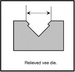
- V dies more than 1 in. (32 mm) wide should have a relieved style (see Figure 3) with decreasing included angles: 85 degrees, 78 degrees, 73 degrees, and so on.
 |
| Figure 3 |
Correct style and angle parameters help to compensate for the increased springback produced by corresponding increases in material thickness and bend radius.
Remember, the complementary angle of the punch must be equal to or less than the included angle of the V die.
Quick to Build
Once the tool profiles are complete, you are ready to write the code, which generally is a fairly easy task. After you've written the code, it's time to head for the laser. A punch press can be used to make a tool, but the final results will be less than stellar both in the quality of the tool and the parts it produces.
Within the code be sure to include one or more holes that will be used for pinning together all of the individual pieces of the tools. Once the tool pieces are cut and deburred, pin the pieces together using a piece of ready rod or doweling. If possible, place the pinned tools under a light load in the press brake or clamp tightly and weld the pieces into solid top and bottom tools. Now dress and clean the tools, and you're ready to form a part.
Results
If you find that your newly produced tool and parts achieve the desired results, you can reproduce the tool with confidence, which in the long run will save you time and money, brightening the bottom line.
With just a little forethought and a laser, you can build custom press brake tooling quickly, easily, and cheaply.
About the Author

About the Publication
subscribe now

The Fabricator is North America's leading magazine for the metal forming and fabricating industry. The magazine delivers the news, technical articles, and case histories that enable fabricators to do their jobs more efficiently. The Fabricator has served the industry since 1970.
start your free subscription- Stay connected from anywhere

Easily access valuable industry resources now with full access to the digital edition of The Fabricator.

Easily access valuable industry resources now with full access to the digital edition of The Welder.

Easily access valuable industry resources now with full access to the digital edition of The Tube and Pipe Journal.

Easily access valuable industry resources now with full access to the digital edition of The Fabricator en Español.
- Podcasting

In this episode of The Fabricator Podcast, Caleb Chamberlain, co-founder and CEO of OSH Cut, discusses his company’s...
- Trending Articles
1
AI, machine learning, and the future of metal fabrication

2
Employee ownership: The best way to ensure engagement

3
Dynamic Metal blossoms with each passing year

4
Steel industry reacts to Nucor’s new weekly published HRC price

5
Metal fabrication management: A guide for new supervisors
