


Oversized V dies: the effects on bottom bending
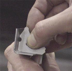 |
| Figure 1 |
Why are so many press brake and tooling manufacturers adamant that you cannot bottom-bend with their products?
One word: Liability!
It's so easy to upset* a ram or blow tooling if bottom bending is done incorrectly. So who can blame the manufacturer for not recommending the process?
Selecting the V die is the most important consideration in any bending operation. To make the proper selection, you must understand how the die performs in different bending methods.
Arguably, the skills required to air-form are less than those required to bottom-bend correctly. Air forming requires patience and the fortitude to check and adjust bend angles and dimensions constantly. Bend angle and dimension fluctuations often are made worse by selecting a punch without taking into account the punch radius's relationship to material types and thicknesses.
The punch-material relationship also affects bottom bending. Using the wrong V-die can damage the press brake or the punch and die sets. Ironically, in some ways, improper V-die use also can be advantageous in bottom bending.
The Eight Times Rule
The common rule in V-die selection is eight times the material thickness is the correct V-die opening. Is this true? Yes, but only in cases in which the material thickness is equal to the punch radius. The rule is invalid in all other cases. For example, using the eight-times rule with 0.050-in. material would require a 0.400-in. V-die opening. Will this produce a 3.000-in. inside radius? Not
likely, except in bump forming.
By using the following formula, you can find a geometrically perfect V die:
V-die opening = (Outside radius x 0.7071) x 4.85
Wonderful you say, but so what? Well ... as you vary from a perfect V-die geometry, the situation changes, especially as the die width increases.
Drawing Material Into the Die
As a bend is made, material is drawn into the V die creating, a large radius between the punch tip and the V-die shoulders (Figure 1). As the punch continues into the V die, the V tightens and eventually matches the punch's tip radius. This is true when an optimal V die is used.
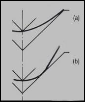 |
| Figure 2 |
When a larger-than-optimal V die is used, the larger radius creates an angular illusion in the finished bend. Note the overbending process as the punch continues through the stroke (Figure 2). Whether you're air forming or bottom bending, the effect is the same.
This is where bottom bending becomes dangerous. If you have ever watched the bottom-bending process, you've seen the material bend past 90 degrees and touch off the punch face before being forced back by pressure.
In air forming, a 90-degree bend is made by forcing the material to 90 degrees plus the springback. The pressure is released and springback "pops" back to 90 degrees. In bottom bending, continued downward pressure forces the material back to 90 degrees.
When the V die is too big, the bend angle cannot be forced back to 90 degrees, no matter how hard the operator tries to achieve the outcome. Applying the force necessary to correct the overbend exceeds the tonnage limit and damages or upsets the press brake and tooling. Using a V die that is too large is the leading cause of this bottom-bending problem.
Springback and the Benefits of Large V dies
Although problems definitely are associated with using larger-than-necessary V dies, doing so can provide benefits in handling springback.
Every material has springback that requires compensation. In air forming, a bend is free-formed to the required angle plus springback. As the forming pressure is released, the material springs back to the required angle.
In bottom bending, springback can be compensated for in two distinct ways. The first is through punch and V-die angles. For example, bottom bending H-series aluminum, which has 1.5 to 2 degrees of springback, requires an 88-degree punch used in conjunction with a 90-degree bottom ( the set angle**) to produce a bottomed bend of 90 degrees. The punch angle allows the material to be formed up to 92 degrees before being forced back to 90 ( the set angle).
Springback also can be dealt with in bottom bending by using a 90-degree sharp punch*** and a 90-degree V die. Say that you're going to bend some electrogalvanized steel, which also has 1.5 to 2 degrees of springback. (Note: You should never sharp-bend aluminum.) The material then is bottom-bent with a 90-degree sharp punch. If you look closely at the bend, you will see the bend angle actually is 88 degrees complementary. But if you put a square on it, the bend will look as if it were a 90-degree bend, because of the extra radius added, as shown in Figure 2.
Although a viable option if executed properly, bottom bending can severely damage a press brake and tooling. The operator must have sufficient knowledge of the process. A simple understanding is not enough. Yes, the material bends up; yes, you can see it as it's forced back. But if that's all you know about bottom bending, you're looking for trouble! Inadequate operator knowledge is the main reason manufactures will tell you not to use this method. Hopefully, this article has shed a light on the subject and inspired you to look a little deeper at bottom bending.
* Upset is when the natural deflection of the ram and bed have become permanent and they no longer will return to the original state.
** In bottom bending, the set angle is the desired angle in the finished bend. It is developed by the included V die angle.
*** A sharp punch is one with a tip radius less than 63 percent of the material thickness.
About the Author

About the Publication

subscribe now

The Fabricator is North America's leading magazine for the metal forming and fabricating industry. The magazine delivers the news, technical articles, and case histories that enable fabricators to do their jobs more efficiently. The Fabricator has served the industry since 1970.
start your free subscription- Stay connected from anywhere

Easily access valuable industry resources now with full access to the digital edition of The Fabricator.

Easily access valuable industry resources now with full access to the digital edition of The Welder.

Easily access valuable industry resources now with full access to the digital edition of The Tube and Pipe Journal.

Easily access valuable industry resources now with full access to the digital edition of The Fabricator en Español.
- Podcasting

In this episode of The Fabricator Podcast, Caleb Chamberlain, co-founder and CEO of OSH Cut, discusses his company’s...


