


The modern mechanical press
Link motion, servo technology, and slide guide advancements
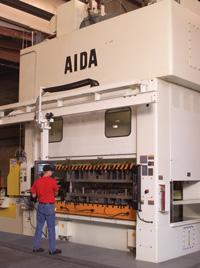 |
| Photo courtesy of Norlen Inc. |
A hydraulic press manufacturer made this statement at a recent trade event: "Most mechanical presses function via flywheel motion with a top dead center (TDC) and a bottom dead center (BDC). Full ram extension and full ram retraction always are at the same points. The retract position and shut height position are somewhat fixed."
To some degree, this statement is true. But for stampers facing the challenges of meeting new end-user demands, it's important to think about mechanical press advancements and the equipment's flexibility for a wide variety of applications.
Choosing a Press Based on Job Requirements
For that reason, it's difficult to define the modern mechanical press. It can, however, be better characterized by a stamper's requirements and by key design advances. Stampers considering a mechanical press should first consider:
- The part or parts to be produced.
- How to improve output and part quality by matching the press model with the appropriate ancillary technology.
Production volume is another deciding factor when choosing a mechanical press. If a stamper needs to draw an 8-inch-deep oil filter can, the choice most likely would be a hydraulic press because of its ability to deliver full tonnage through the entire stroke length and control velocity during draw work. If this part is intended for earthmoving equipment, production volume would be low.
If the requirement is for a 3-in.-deep oil filter can produced at 30 to 50 strokes per minute (SPM), a mechanical transfer press may make the most sense. A part this size used for an automotive application would dictate high volumes at high cycle speeds.
Once these factors are determined, the right mechanical press can be tailored to the job requirements. In addition to being able to deliver the necessary speeds to match stroke and volume requirements, modern mechanical presses have been designed to control the BDC point within a few microns.
 |
| Figure 1 Because the slide doesn't pass BDC, die sticking is eliminated, which makes combination work possible. With a linear scale fitted to the slide, BDC compensation becomes possible and control more precise. |
High-tech Mechanical Presses
BDC repeatability is especially important in high-speed operations that create heat and cause part expansion—conditions that can affect operating shut height and dimensional changes (see Figure 1). A mechanical press equipped with active BDC compensation automatically senses changes in shut height and varies hydraulic pressure in the slide adjustment lock mechanism to maintain correct BDC height and repeatability.
Other advances in mechanical presses include link motion, servo technology, and slide guides.
Link Motion. With the development of link motion, stampers gained the ability to modify slide motion and control velocity through the working portion of the stroke (see Figure 2). When the mechanical press slide is maintained near the bottom of the stroke for an extended period of time, metal forming operations in progressive-die work can be enhanced. Link motion helps to reduce punch velocity by holding pressure on the workpiece longer. Metal has more time to flow because the material is in the work portion of the stroke 30 percent to 40 percent longer than in a conventional crank- or eccentric-motion press.
 |
| Figure 2 Link motion allows stampers to modify slide motion and control velocity through the working portion of the stroke. |
The additional time allows the part to set dimensionally. Typical springback is reduced, and dimensional stability and accuracy are improved without lengthening overall cycle times. The slide then regains the extra time spent at the bottom of the stroke as it travels over the top, which can improve part accuracy and lower die costs. The need for secondary forming and assembly operations also can be minimized.
Servo Technology. The newest technology allows stampers to program slide motion fully, including stopping it at any point during the stroke. Some examples of this programmability are:
Knuckle— A slow-touch knuckle motion increases working time without cutting production rates. Die life also is increased by reducing die impact.
Slowdown— Many applications require multiple operations. When the slide is slowed at the top of the stroke, automation systems can be synchronized while maintaining suitable forming speed and maximizing cycle times.
Short Stroke, Higher Speed— The ability to set minimum stroke length to match the work can shorten the working cycle through higher press speeds.
Dwell at BDC— Stopping the slide before BDC eliminates die sticking and makes multiple operations possible. Combination jobs such as tapping within the die and part mounting can become easier.
Crank Motion— Servo technology operates as a traditional crank-motion press for high production rates with high control.
This type of programmable slide motion uses a direct-drive design that houses a high-torque, low-RPM servomotor (see Figure 3). Direct drive also provides the same maximum stroke length and torque rating as a conventional mechanical press, while allowing full torque to be used at 5 SPM. Full torque at low speeds allows stampers to perform forming operations at slide velocities that typically cannot be achieved.
Slide motion programmability and capacitor banks may help reduce operating costs and lower power consumption. Huge capacitors store energy when the servomotor is not under load. When the motor is loaded, power is drawn from the capacitors and not the main line.
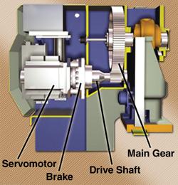 |
| Figure 3 Original direct drive connects a high-torque, low-RPM servomotor directly to the crank for high speed and working energy, control and accuracy, and reduced power usage and maintenance. |
Slide Guides. Mechanical press accuracy has improved dramatically with updated guiding systems. Because the slide is able to closely control punch motion and the relationship between the punch and die, the press is more accurate than the die set. One recent improvement has been the introduction of lubrication-free, preloaded roller bearings in slide guide systems.
Because preloaded roller slide guides are lubrication-free, the potential for press oil contamination of a part is eliminated. Dry slide guides are different from standard high-speed slide guides because they use a roller bearing mount with the ability to swivel. This capability helps the rollers maintain contact with the guide surface on the column during off-center load situations.
Lubrication-free, preloaded roller bearing slide guides now make it possible for manufacturers to use a straight-side press to produce a variety of stampings, from high-volume, thick progressive-die parts to larger, lower-volume, highly cosmetic pieces.
A recent development in precision slide guiding is a preloaded, zero-clearance slide guide system with high-pressure oil lubrication. This development is directly aimed at improving press accuracy.
Some common problems in stamping operations are slide tipping caused by high off-center die loads; slide shimmy caused by shock at the point of contact between the punch and material; and snap-through at the time the material fractures. Precision slide guiding may help a press counteract these problems.
The guides consist of spherical shoes operating against flat guideways attached to a frame structure. Because the press slide is tall, guide points are spaced apart for long slide guides. The surfaces of the mating components are made from materials that possess natural lubricity. Oil is then forced between these preloaded surfaces. This combination of preload and oil lubrication helps make the slide guide stiff and provides long life with little or no wear.
End-user demands for new product configurations, materials, and press capabilities will continue to have an impact on the metal forming area, and mechanical press design improvements and flexibility need to keep pace with stampers' changing applications.
About the Author
About the Publication

subscribe now

The Fabricator is North America's leading magazine for the metal forming and fabricating industry. The magazine delivers the news, technical articles, and case histories that enable fabricators to do their jobs more efficiently. The Fabricator has served the industry since 1970.
start your free subscription- Stay connected from anywhere

Easily access valuable industry resources now with full access to the digital edition of The Fabricator.

Easily access valuable industry resources now with full access to the digital edition of The Welder.

Easily access valuable industry resources now with full access to the digital edition of The Tube and Pipe Journal.

Easily access valuable industry resources now with full access to the digital edition of The Fabricator en Español.
- Podcasting

In this episode of The Fabricator Podcast, Caleb Chamberlain, co-founder and CEO of OSH Cut, discusses his company’s...
- Trending Articles
1
Steel industry reacts to Nucor’s new weekly published HRC price

2
How to set a press brake backgauge manually

3
Capturing, recording equipment inspection data for FMEA

4
Are two heads better than one in fiber laser cutting?

5
Hypertherm Associates implements Rapyuta Robotics AMRs in warehouse
