


Technical Writer
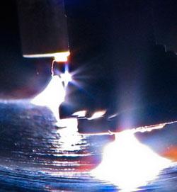
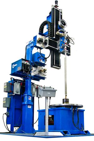
Figure 1: In this automated setup, dual hot-wire GTAW torches clad two layers of INCONEL® 625.
Now that all the “easy oil” has been extracted, offshore operations will become more important to meet the world’s energy needs, and with that never-ceasing demand comes the need for cladding. The oil and gas sector will continue to demand clad products that are produced quickly and, most important, of extremely high quality. In this arena, automated cladding and advanced inspection systems will play a vital role (see Figure 1).
Corrosiveness depends on the levels of hydrogen sulfide (H2S), carbon dioxide (CO2), and chlorides from saltwater in the oil. Sour crude contains substantial amounts of these corrosive elements, and as pressures and temperatures increase in deepwater wells, corrosiveness increases as well.
In steel, corrosion leads to hydrogen embrittlement, which can cause catastrophic failures in amazingly short order. On a molecular level, hydrogen embrittlement occurs when hydrogen ions (H+) infiltrate the grain boundaries of steel and then recombine into molecular hydrogen (H2), which weakens the bond strength in the steel’s crystalline lattice. Embrittlement occurs where cracks begin to form and cause material failure even when the steel is subjected to tensile stresses well below the steel’s normal yield strength.
Pitting corrosion and crevice corrosion are the most detrimental forms in stainless steel pipelines. Pitting occurs particularly when chlorides are present, such as in sour crude containing seawater, where small pits begin to grow along the inner surface of the pipe wall and eventually perforate the pipeline. Crevice corrosion occurs in any slot or groove where the corrosive element can lodge itself, such as in the overlapping boundary between two lengths of steel pipe.
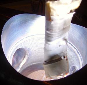
To mitigate corrosion, engineers clad corrosion-resistant alloys (CRAs) to surfaces that contact sour crude. Cladding fuses two metals to combine their properties (see Figure 2). CRAs are vital because they have chemical properties that block hydrogen ions and other corrosive accelerants.
Clad pipe, also known as overlay pipe, is manufactured by cladding a layer of CRA to the steel pipe’s inside surface. This produces a pipeline with the structural strength of steel and the corrosion-resistant properties of the CRA along the inner wall.
Hot isostatic pressing (HIP) was one of the earliest processes used to clad the inside walls of pipes. A valve body was machined with an allowance of space for a layer of CRA. Then a tooling procedure known as canning used a series of tubes and flanges to create an internal lining with a vacuum-tight pocket of space against the wall of the valve body. This pocket then was filled with powder-metal CRA, such as INCONEL 625. The part was loaded into an autoclave and subjected to temperatures up to 2,000 degrees F and gas pressures up to 15,000 PSI, which bonded the CRA to the base material.
HIP was limited by the size of the autoclave required to create a pressure chamber, making cladding difficult for large valve bodies. Canning also had limitations when faced with complex geometries. And, overall, the process was costly and time-consuming.
Gas metal arc welding (GMAW) replaced HIP to allow for the cladding of larger, more complex valve bodies. GMAW feeds consumable CRA wire across the arc into a molten puddle shielded with inert gas. Though increasing the wire feed speed produces higher deposition rates, it also generates more heat, causing the weld puddle to penetrate deep into the base metal. Penetration in the base metal dilutes the CRA with iron content, compromising the metallurgical properties of the CRA layer. Short-circuit-transfer GMAW cladding helps decrease iron dilution and heat input, but is notorious for lack-of-fusion defects between the CRA and base metal.
Gas tungsten arc welding (GTAW) solves lack-of-fusion issues. In GTAW cladding, a tungsten electrode maintains the weld pool and the CRA wire feeds separately into it. Unfortunately, deposition rates plummet because the cold wire introduced at ambient temperature essentially quenches the weld puddle.
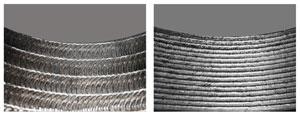
Figure 6: Oscillating the head produces the clad beads on the left. Laying down stringer beads, as on the right, can cause problems at high deposition rates because the clad metal solidifies beyond the shielding gas, opening the door for severe oxidation.
All this led to today’s dominant cladding process, hot-wire GTAW. The process adds a second, separate power supply to heat the wire near its melting point as it is introduced to the weld puddle. This effectively doubles the deposition rates of conventional, cold-wire GTAW.
Quality has always trumped deposition rates when weighing the economics of cladding. This is why hot-wire GTAW—fast compared to cold-wire GTAW but still slow compared to other processes—has remained dominant in industry. Rework on a defective part requires expensive machining of CRAs, which are difficult to remove. The extra time erases any productivity advantages from using higher-deposition-rate processes. Moreover, parts can be heat-treated only so many times before their base metal properties are compromised. This limits the number of times parts can be reworked. Consequently, if the defect rate in a plant increases by even 1 percentage point, operation managers will do just about anything, including sacrificing deposition rate, to make the defect rate go down.
Hot-wire GTAW also can work in all positions, allowing access to components of different sizes and complex geometries. And, generally, hot-wire GTAW equipment costs less than the systems required for the process’s most recent contenders, such as laser cladding.
Modern automation systems are designed to provide repeatable quality and minimize defects. Vertical-bore cladding operators now teach a new part to the cladding system by entering basic geometry data such as the diameter and location of intersecting bores (see Figure 3). The system then knows where to stop and resume cladding as it intercepts the bore, which maximizes duty cycle time, or arc-on time, and increases productivity (see Figure 4).
Such turnkey cladding systems can store qualified weld schedules, offer touchscreen interfaces, and are built with closed-loop process control that gives real-time feedback on heat input and other clad parameters. Automatic voltage control maintains constant arc length throughout the operation.
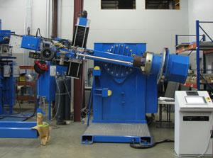
Bore cladding in the horizontal position (1G pipe) as opposed to the traditional vertical position (2G pipe) sometimes can double deposition rates. Operating in the 1G pipe position allows gravity to hold the puddle so it can become larger; this means weld travel speeds can increase. Instead of using turntables, though, such setups fixture parts using a three-jaw chuck. This limits horizontal cladding to symmetrical parts that can be chucked, such as short tubulars.
To accommodate a variety of parts, hybrid cladding systems can work both horizontally and vertically (see Figure 5). One hybrid system’s approach uses a swiveling torch head and pivoting three-jaw chuck so the system can switch between horizontal and vertical positions. Another method fixes a chuck and torch head onto a rotating cradle, which allows the torch to clad horizontally, vertically, and at various angles in between.
Oscillation increases the deposition rate further when cladding horizontally. Attempting the hot-wire process at high deposition rates using traditional stringer beads results in the bead solidifying beyond the shielding gas, which causes severe oxidation. At high travel rates, oxide buildups will cause oxide inclusions, or lack-of-fusion defects, in subsequent layers. Oscillating the head requires the part to rotate slower, spreading the puddle and heat input while still maintaining wire speed (see Figure 6).
Oscillation also creates a wider bead with less dilution and better bead-to-bead tie-in. Moreover, wider beads reduce the overall number of bead-to-bead interfaces in a part, which is ideal for heat-induction bending on clad pipe.
Another approach to double the deposition rate when cladding pipe is to use two hot-wire GTAW torches in tandem to clad two layers of CRA in one pass (see Figure 1). A head with two torches in line with each other attaches to an extension arm that inserts into a rotating pipe, where the torches produce a continuous circumferential clad. The extension arm also can oscillate if needed.
Gas Mixtures
The correct shielding gas mixture helps push deposition rates in hot-wire GTAW. In the early days, helium was the shielding gas of choice, but because of cost and because helium often made consistent arc length difficult to maintain, the industry moved toward argon.
Helium, however, has high ionization potential, which produces more volts per given arc length, more heat input per given unit area, and, because of this, higher deposition rates. For this reason, engineers now customize argon-helium blends to balance the cost-effectiveness of argon with the high-deposition qualities of helium. Mixing helium with argon also reduces the number of fusion defects from oxidation.
No matter how advanced cladding technology becomes, all the efficiency gained is for naught if nondestructive testing misses a defect or misinterprets clad characteristics. For instance, ultrasonic testing often misinterprets irregular bond lines as defects, and has difficulty detecting fusion-zone nuances between a very thin layer of CRA clad and a thick base of a dissimilar metal.
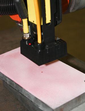
Liquid penetrant testing (LPT) involves marking defects with dye blotches known as indications, which form after a liquid penetrant is applied. The dye, however, has been known to wash out of large defects, leaving them undetected. The indications left by liquid penetrant can be difficult for technicians to see inside pipes. Inspectors often use flashlights and mirrors to peer down into clad pipe to estimate whether or not an indication’s size is within very tight tolerances.
In these cases, automated liquid penetrant (ALP) inspection systems can help. These incorporate CCD cameras and software to scan clad pipe in search of dye indications in the clad (see Figure 7). Used after the dye is placed on the workpiece, these systems trace the perimeter of a dye indication, calculate the precise area, and give a pass/fail grade based on user-defined tolerances set within the software (see Figure 8). Each indication’s location and size are recorded in a log along with inspection data for quality records and repair work. To fully automate dye inspection, ALPs can be integrated with robotic systems and other motion control systems.
Defects missed by ultrasonic testing or are too large to retain dye in LPT can now be captured using profile mapping tools (PMTs). These use an automated rotating laser head with a single-point displacement sensor to measure deviations in distance inside the pipe. The PMT software correlates data from the laser scan to generate a 3-D, false-colored image of the pipe’s inner surface. The software then records any defects located in the pipe with respect to user-defined tolerances (see Figure 9).
The system can detect surface roughness, pitting, voids, porosity, and cracks, and can visualize and quantify them with real-time radius feedback, generally with a resolution of 0.002 in. Single-head laser scanners can scan clad pipe with an inside diameter from 4 to 10 in., though systems can scan additional sizes using specialized laser sensors or laser-line-scan displacement sensors.
Continual process optimization will keep hot-wire GTAW viable. Increased demand for niche components may call for cladding systems that don’t have the flexibility of hot-wire GTAW, but do offer very high deposition rates. In these instances, cladding with pulsed GMAW—a high-deposition-rate process—could fill the need. Computer-controlled algorithms and synergic pulsed waveforms inside new GMAW equipment have improved process control tremendously—so much so, in fact, that pulsed GMAW may be viable even for certain critical cladding applications.
Ultimately, technology advancements will follow two tracks: One will lead to machines that produce faster, better clads; the other will involve better inspection systems that ensure clad parts put into service are as flawless as possible. In a sense, the full potential of better cladding equipment can’t be realized without better inspection. And today both are meeting industry’s demand for component reliability and longevity.

The Fabricator is North America's leading magazine for the metal forming and fabricating industry. The magazine delivers the news, technical articles, and case histories that enable fabricators to do their jobs more efficiently. The Fabricator has served the industry since 1970.
start your free subscription
Easily access valuable industry resources now with full access to the digital edition of The Fabricator.

Easily access valuable industry resources now with full access to the digital edition of The Welder.

Easily access valuable industry resources now with full access to the digital edition of The Tube and Pipe Journal.

Easily access valuable industry resources now with full access to the digital edition of The Fabricator en Español.
In this episode of The Fabricator Podcast, Caleb Chamberlain, co-founder and CEO of OSH Cut, discusses his company’s...


