


Senior Applications Engineer

Figure 1: Self-shielded flux-cored arc welding is used often for out-of-position work.
Self-shielded flux-cored arc welding (FCAW-S) wire is the industry’s multitasker. All at once it produces its own shielding to help protect the arc, handles contaminants on the steel, deposits weld metal that meets structural requirements, and forms a fast-freezing slag over the weld metal.
FCAW-S is more like shielded metal arc welding (SMAW), or stick, and less like other gas-shielded wire processes. Welders experienced in SMAW often pick up FCAW-S quickly, while those who know only short-circuit gas metal arc welding (GMAW) may take a little longer.
Like SMAW, FCAW-S does not use an external shielding gas, so it is convenient for outdoor work (see Figure 1 and Figure 2). However, unlike SMAW, the self-shielded flux-cored process offers much higher productivity levels. Deposition rates are equivalent and, in some cases, exceed those achieved with gas-shielded wire welding. With stick electrodes like E6010 and E6013, you might deposit 2 to 3 pounds of metal an hour. With SMAW electrodes such as E7018, that might jump to 4 to 5 lbs. an hour. However, with FCAW-S, you could deposit up to 8 lbs. an hour out of position and more than 12 lbs. an hour downhand (that is, flat and horizontal positions), depending on the wire used. In fact, working with some wires, using extended electrical stick-out procedures, you can deposit more than 20 lbs. of weld metal an hour.
GMAW (MIG) and most gas-shielded flux-cored (FCAW-G) wires weld best on direct current electrode positive (DCEP). The recommended or most stable polarity for FCAW-S, though, depends on the specific core elements (arc stabilizers) in a particular wire. Most FCAW-S wires work best in direct-current electrode-negative (DCEN) polarity, but a few are most stable with DCEP.
In GMAW, a smooth V-groove in the wire feeder’s drive rolls grips the solid wire to feed it through the welding gun. Unfortunately, the smooth V-groove’s tight squeeze can deform cored wires. To attain the same pushing force without squeezing so hard, FCAW-S wires require knurled V-groove drive rolls that grip the wire sheath, providing pushing force without deforming it.
Note, if you do switch back to GMAW after FCAW, be sure to change your wire feeder to the smooth V-groove drive rolls. Knurled drive rolls can dig into the copper coating on solid GMAW wires and cause them to flake. This problem often is not as pronounced as it used to be, but it is still a concern.
All self-shielded flux-cored wires are sensitive to changes in voltage and so require a constant-voltage (CV) power source for good arc stability. Depending on the application, gas-shielded processes may give you a wider voltage window, which still produces satisfactory results. However, with FCAW-S, you must properly dial in the correct voltage for the job at hand.
In the self-shielded process, once the arc ignites, nothing lies between molten weld metal and the atmosphere except for the slag and internally produced shielding gases. Higher voltages increase the arc length, which in turn broadens the arc cone or arc width. This longer, broader arc has more exposure to the atmosphere. Proper arc length is paramount, and CV power sources help maintain that constant arc length.
Note that when exposed to air (which contains 79 percent nitrogen, 20 percent oxygen, and 1 percent other elements), molten metal naturally absorbs nitrogen and oxygen. If allowed to do so, some of these gases will escape as the metal freezes, but will leave behind excessive holes (that is, porosity). The remaining trapped gases create very brittle weld metal with poor mechanical properties. The molten metal must be protected, or shielded, from the atmosphere until it solidifies. These basic facts never change regardless of which arc welding process you use.
Now imagine a molten droplet of weld metal detaching from an FCAW-S wire. Almost immediately a thin slag layer forms around it. In the wire’s core are elements that chemically combine with the nitrogen and oxygen (that is, denitrifiers and deoxidizers) and pull them into the slag, thus preventing them from being absorbed into the weld metal. Other gases are produced as well, such as carbon dioxide, as byproducts from chemical reactions in the arc, which help displace the air. Both systems protect the molten metal droplet during its journey to the weld pool.
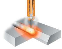
Figure 3: A self-shielded FCAW wire has an outside sheath covering a core of fluxing agents that protect the weld. It’s a bit like a stick electrode, but turned inside out.
The longer the arc length, the farther those droplets must travel and the greater their exposure to nitrogen, oxygen, and other atmospheric impurities. If it is too much for the wire’s protection system to handle, the excess will be absorbed into the weld metal. Those impurities in turn affect the resulting weld’s mechanical properties, including impact toughness. A Charpy V-notch test should make this abundantly clear. When the amount of impurities reaches a certain point, you end up with porosity. Meanwhile, a too-low voltage creates a too-short arc. This causes the wire to stub into the plate, producing a cold, ropy bead profile.
Flux-cored wires naturally form a small ball of slag over the end of the wire after each weld. The slag acts as an insulator and prevents good electrical contact for starting. So to ensure good arc starting, you must break off the end of the wire cleanly (which can work for certain rod-based wires) or snip it smooth.
Be sure your electrode extension, or electrical stick-out, is correct. The wire should extend 0.75 to 1 inch from the contact tip for standard welding procedures, and sometimes up to 3.75 in. for very high-deposition downhand welding. Just as arc length is critical, so is electrode extension. It should be maintained at a consistent length (within ±0.125 in.) for good arc stability. An extension that is too long will produce a short, unstable arc with excessive spatter, while an extension that’s too short will cause excessive arc length and open the door to impurities from the atmosphere.
Also, never push the electrode. This is not short-circuit GMAW. The self-shielded process uses slag, so you can follow the old rule: Push gas, drag slag. Placing the gun at a slight drag angle keeps the slag behind the arc. Angling the gun forward tends to push or force the molten slag to the front of the weld pool, increasing the chances of it rolling ahead of the metal and being trapped underneath.
The specific wire used makes a big difference in deposition rates and in overall process characteristics. Wires with the AWS classification E71T-8—those good for all positions using DCEN polarity—all produce similar metallurgical results, but grouped under this AWS classification are different wires with their own idiosyncrasies.
The most prominent differences come from the wires’ slag systems. These consist of materials that chemically react with other elements, freeze before the molten metal, and rise to the top to protect the molten weld bead from the atmosphere (see Figure 3). Some wires have a basic fluoride slag system, similar to that found in SMAW electrodes like E7018. Others have a more acidic oxide system that chemically reacts and freezes faster, helping welders achieve those fast, 8-lb.-per-hour, out-of-position deposition rates. (For more on slag systems, see Technical Brief: Insight on Slag Chemistries sidebar.)
Technique depends on the wire make; for specific advice, consult the wire manufacturer. Technique also depends on the base metal and application, but you can count on several general characteristics when using certain wires.
For instance, consider two versions of E71T-8 called Innershield® NR-203MP or NR-203 Nickel (1 percent), which use a basic fluoride (nonacidic) slag system. Welding with NR-203 wires resembles E7018, though the wires offer higher deposition rates and, of course, eliminate the need to change out rods.
When welding a groove or fillet out of position with NR-203, use a weave technique. Point the wire at the toes of the weld bead and pause slightly—to obtain good penetration and give time for the slag to rise out of the toes—then move quickly across the weld face before pausing momentarily again at the opposite toe. Dwell too long in the center and you risk depositing too much weld metal and producing an excessively convex bead that not only affects a joint’s mechanical properties, but also leaves the bead susceptible to defects such as undercut.
Always be sure to keep a good focus on the weld pool. This weave motion—pausing at the toes then moving quickly across the face—allows weld metal to wash in from either side. The momentary pause at one weld toe also gives time for the slag to freeze at the other toe. Relative to other self-shielded wires, NR-203 uses a thin slag that can hold only so much weld metal, which is why you can deposit only 5 to 6 lbs. of weld metal per hour—faster than stick, but slower than other self-shielded wires.
This includes NR-232 and NR-233. These wires have an acidic slag system that reacts very quickly in the molten metal and produces a heavier slag, allowing for higher deposition rates.
Unlike when welding with NR-203, when you really watch the weld pool, with NR-232 and NR-233 you focus on the slag line forming behind the arc’s leading edge. Instead of a traditional weave, use a stringer bead with a slight wiggle. If that slag line is not level, you may take some quick corrective action. For instance, if the slag line is lower on the left side, move the gun slightly to the left to even up the slag line, and then continue the wiggle-stringer technique up the joint. When welding vertical-up, think as if you are building a shelf of weld metal, stacking the weld beads one on top of the other.
How fast you stack determines your travel speed. If you travel too quickly and place the arc slightly beyond the weld pool, the wire tends to dig into the plate and perhaps even burn through.
Heat control is also critical, and to do this you can alter the electrode extension, a technique common not only to FCAW-S, but also to all wire welding that uses a CV power source. If, say, you are welding vertical-up, riding on a shelf of molten NR-232 weld metal, you may sense that the pool is getting a little too hot and your arc is digging into the plate. In this case, you can add a little stick-out, which drops amperage and cools the weld pool slightly. Vice versa, if the process is a little too cold and you are not penetrating enough, you can shorten the stick-out slightly, which increases amperage and allows you to dig a little harder.
In a nation striving to upgrade its infrastructure, FCAW-S has become the process of choice for many. It combines the efficiency of wire welding with the portability and flexibility of SMAW. It usually is not the first process a welder learns, but if perfected, FCAW-S can be one of the most effective.
In self-shielded flux-cored arc welding, slag systems predominantly consist of aluminum-magnesium deoxidizing and denitriding elements. They enter the weld pool and form aluminum oxide and magnesium oxide, two compounds with high melting temperatures. Combine these with low-melting-temperature elements in the flux and you get an effective slag system. The slag elements—aluminum oxide and magnesium oxide—freeze first and float to the top of the molten weld pool along with other fluxing additions, protecting the process from atmospheric contamination.
FCAW-S has a very high tolerance for nitrogen, and the slag system makes this possible. The aluminum and magnesium molecules attract oxygen and nitrogen atoms, which connect to form those aluminum and magnesium oxides. These high-melting-point (that is, fast-freezing), lightweight compounds float to the weld surface quickly. In effect, the slag system transforms oxygen and nitrogen—potential contaminants—into chemical compounds that protect the weld.
Many FCAW-S wires use one of two types of slag systems: basic fluoride and acidic oxide. In basic fluoride systems, calcium fluoride works together with the aluminum and magnesium compounds, creating a system that somewhat resembles the slag produced when welding with some SMAW electrodes, such as E7018. Acidic oxide systems, on the other hand, use a combination of acidic oxides (for example, iron oxide, silica, and alumina) and basic oxides (for example, calcium oxide and magnesium oxide), instead of a predominantly fluoride-based slag system (calcium fluoride).
The basic fluoride systems have good cleaning action and tend to be suited for structural-critical work, meeting low-temperature toughness and other stringent mechanical property requirements. Acidic oxide systems promote smooth, fast welding.
The reason behind this has a lot to do with how the acidic oxide and basic fluoride elements react with other weld metal elements. It comes down to how easily chemical reactions occur. During welding, molecules are ionized, meaning atoms leave certain molecules to join others, and specific slag systems require different levels of heat to accomplish this. In fluoride systems, a lot of heat goes into breaking up these molecules to form fluoride bonds. Meanwhile, it doesn’t take quite as much heat to break up the acidic iron-oxide molecules in the presence of highly deoxidizing elements such as aluminum and magnesium. The quick reaction leads to fast slag freezing and, ultimately, high deposition rates.
Information provided by The Lincoln Electric Co.

The Fabricator is North America's leading magazine for the metal forming and fabricating industry. The magazine delivers the news, technical articles, and case histories that enable fabricators to do their jobs more efficiently. The Fabricator has served the industry since 1970.
start your free subscription
Easily access valuable industry resources now with full access to the digital edition of The Fabricator.

Easily access valuable industry resources now with full access to the digital edition of The Welder.

Easily access valuable industry resources now with full access to the digital edition of The Tube and Pipe Journal.

Easily access valuable industry resources now with full access to the digital edition of The Fabricator en Español.
In this episode of The Fabricator Podcast, Caleb Chamberlain, co-founder and CEO of OSH Cut, discusses his company’s...


