Chairman, WTIA Project Panel #1 (Pressure Vessels), Inspection and Integrity manager
Author's Note: This article originated as a conversation in which I explained why I should not present a paper on refinery welding—that the problems are mostly mundane, and that high-tech solutions are only rarely if ever sought or needed. Solving problems mostly comes down to common sense and good communication. I can only assume that it struck a chord, because a few days later I was nominated to present a paper entitled "Refinery Welding as a Way to Get out of the Place Between a Rock and a Hard Place. I must therefore start by acknowledging Dr. Harry Moss, who wore out his keyboard in suggesting a title for this article.
 |
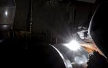
| A common welding repair technique used in refineries is to weld a patch plate or sleeve onto equipment that is still operating and under pressure. |
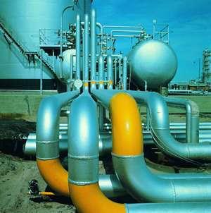
A refinery is a complex array of pressure vessels, piping, structural carbon steel, and other components that depends on welding for its structural integrity. A minor problem can have enormous cost and safety implications.
However, when we consider the many miles of welds that go into the makeup of a refinery, we can only be impressed by how little goes wrong. This underscores the point that standard welding techniques can do the required job when appropriately applied and correctly managed.
Great care is required in a repair situation. Sometimes I can only marvel at the welder's ability to align his body, helmet, eye, and welding rod with the job to make a weld in the first place.
If the repair is undertaken because of internal corrosion, it is necessary to find a line around the most severely corroded section with wall thickness adequate for the weld to proceed safely. This usually is performed using ultrasonics. As a rule of thumb, the minimum pressure is the wall thickness plus 2.5 millimeters, but not less than 4.8 mm.
Particular care must be taken with pitting corrosion, and in some cases with erosion, because thinning can be local, making a continuous scan essential.
A common welding repair technique used in refineries is to weld a patch plate or sleeve onto equipment that is operating and under pressure. This weld method is similar to that used for hot tapping, in which a nozzle with a valve is welded onto the parent material, usually a pipe, and a hole is cut in the parent by drilling through the valve.
In some instances the patch plate to be welded on follows an irregular path. One of the issues with such a technique is that, in order to reduce the risk of burn-through, the parent pipe must be kept cool by establishing a flow through it. This assumes that the weld is being quenched as it progresses. But sometimes keeping the parent pipe cool is out of the question.
In one actual case a cracked and leaking girth weld in a 10-inch (250-mm), 450-pounds-per-square-inch (PSI), superheated steam line was repaired online by welding a full encirclement sleeve around it. The steam leaking around the weld zone ensured that it was anything but low-hydrogen welding; nevertheless, it still is in service, about 20 years on. (The welder got his just reward—he now is my manager!)
Likewise, in another case a series of patches were welded onto a 30-in. (750-mm) fluid catalytic cracking unit (FCCU) fractionator feed nozzle, with a metal temperature of 249 degrees C (480 F). This was internally eroded in a number of localized areas. In this case the pressure was small but the hydrocarbon content was well above its autoignition temperature. The nozzle repair demanded high confidence about the thickness along the entire weld line.
For pipe, an assessment should be made as to whether a repair requires a full sleeve or if a half sole (patch plate) is sufficient. If hoop stresses are high, longitudinal welding usually is not advised. A split sleeve can be installed, first welding the two halves together, ensuring the weld does not intrude on the pipe wall. Then each end is welded to the pipe.
If half soles are used, they should be closely fitted to the pipe, and any external corrosion should be filled with a resin or another fill material to achieve optimum strength.
Most of a refining plant is constructed of carbon steel. However, a small but significant smattering of steel alloys and other materials also is used. When these materials require repair, it can be difficult to obtain material samples to perform welding tests.
In one situation a cracked pump casing made of 410 stainless steel needed repair. Available weld procedures specified using a high-nickel welding consumable, but a mix of austenitic and ferritic materials was considered inappropriate for this service (thermal cycling) even though their coefficients of expansion are similar.In this instance we were able to obtain material from cast hollow billets that were used to make pump wear rings, and we were able to qualify a procedure. The weld deposited for testing was far more than the 2 in. (50 mm) or so that had gone into the repair!
It is not always possible to find a material sample for weld procedure qualification. When purchasing equipment made of unusual materials, we have adopted a policy of requesting that any available surplus material be supplied to us.
In a case involving a large, heavy-walled hydroprocessing reactor, we were able to obtain sections of welded shell left over from the production test pieces. We examined one to assess the optimum postweld heat-treatment procedure and placed another in the reactor so that we could monitor its performance.
Frequently weld repairs are repeated in the same location. Repeated thermal cycles could have an adverse effect on the material properties.
Also, storage tank floors may be replaced several times over the life of the tank, and the area where the floor is welded to the shell undergoes significant stress cycles. This is especially true in high-temperature plants where repairs and modifications add a great number of thermal cycles, particularly when the repairs are done on stress-relieved alloy piping.
Other potential problem areas are where pipe already has deteriorated from temper embrittlement or hydrogen damage. Although few or no failures have occurred, research on these effects would be useful.
The friendly nature of nickel-alloy welding consumables has led to their use for many types of repairs. The INCONEL® alloy 182 electrode is so forgiving that it has been referred to as "the rod from God." Quite a mythology has arisen around this alloy, and it has been proposed for (and perhaps used for) applications such as 5Cr materials without preheat or postweld heat treatment.
Vigilance is essential to ensure that such abuse does not occur, or, better still, to educate those who may be tempted to follow such a course of action. One instance in which it did not serve well was for welding an austenitic 304 sleeve to a ferritic 410 casting. This application was a critical component of a catalytic cracker regenerator that operated at about 370 degrees F (700 degrees C).
Despite the great care that was taken in the welding and heat treatment of the assembly, the two components always parted company after some time in operation.
The cast component was the subject of another myth—that the casting had to be ferritic. Once this ferritic casting was changed to a matching austenitic casting, no further problems occurred.
We have seen evidence that high-nickel rods can produce hard microstructures when used on ferritic steels—including plain carbon. We performed a series of tests to establish how best to weld carbon steel brackets to a low-chrome-alloy shell. High-nickel chromium alloy and carbon steel rods were assessed.
Postweld heat treatment was impossible, and preheat was limited. (We didn't want to cook the welder!) The best result was obtained using a standard carbon steel 7018 rod (4818 in metric notation)—the welds have been in place now for more than 10 years.
Weld hardness may be of particular interest in several areas in a refinery. These include sour service and corrosive duty such as in an HF alkylation plant, where a hardness limit of 200 HB usually is specified.
This usually is easily achieved on a pipe inner wall welded from one side as each weld bead tempers the bead below. However, corrosion behavior of welds in HF units can be extremely unpredictable.
In one case severe corrosion occurred in a closing field socket weld where the inner wall was 140 HB, at least where it was adjacent the area corroded away. Of course, in most cases the production hardness of the inner surface cannot be measured.
At the time there was some suspicion that inaccurate settings on welding generator sets could contribute to variations in hardness. Informal tests were conducted using a digitally controlled welding machine. They showed that within the bounds of weldability, current caused little hardness variation.
Regarding chrome-molybdenum alloys, a hardness limit of about 230 HB often is specified. Measurements sometimes result in dispute. It is important to be aware of the sort of accuracy achievable with a field hardness tester and to be quite certain about why the test is performed.
The accuracy of some measurement methods is highly questionable. For example, the Tellebrineller was the mainstay of hardness testers in refineries for many years. With a Tellebrineller, a hardened ball was held between a bar of known hardness and the test piece. The bar was struck so that the ball impressed both bars. Then the sizes of the impressions were compared to give a hardness value.
Such a device can give little more than broad information to determine if the weld was heated after welding and hardly allows for accurate placement of the test, in the heat-affected zone (HAZ), for example.
However, the industry has survived well with such devices. This leads to questioning the need for accurate field information—which is not to imply that accurate information is never required. Modern portable instruments also have their drawbacks. It is important to understand exactly what each measures and what the information obtained means, particularly if a weld is to be rejected on the grounds of that instrument's accuracy.
Acceptance Criteria: Workmanship Standard or Service Standard? Setting acceptance criteria in repair welding can be a matter for fine judgment. To illustrate, an HF alkylation unit frequently had delayed leaks from pinholes in socket weld joints after repair and after project welding. The hydrofluoric acid (HF) slowly dissolved slag remaining in the weld, resulting in sporadic leaks containing HF, which is a lethal substance, over the next two or so years.
This problem was overcome simply by close supervision and communicating the need for uncompromised quality to the contract welders.
On the other hand, occasionally a zealous engineer has insisted on cutting out a weld that has failed radiographic inspection on account of a code noncompliance. One time this happened even though the weld was clearly fit for the intended service.
This is perhaps a problem we will have to live with more and more. Engineers are increasingly driven by fear of litigation to rigorous compliance with a code that does not pretend to address every issue that crops up and is usually written for new fabrication rather than field repair situations. Such code probably can be regarded more as a workmanship standard than a service standard.
Things that go wrong often have more to do with communication and management than with deficient technology. The key to ensuring that work is performed correctly is being clear about what is required and ensuring that this is clearly communicated the whole length of the work chain.
Know what is needed, understand the implications of what you don't know, and communicate to those who need to know.
I will conclude with a final anecdote. It has nothing to do with welding, so forgive me, but it perfectly illustrates my point:
In one refinery about 200 glass tubes had to be removed temporarily from an air preheater and stored. The tubes were fairly costly—about $130 each—but more significant, they were unobtainable at that time.
Each tube was carefully removed from the tube sheets, passed along carefully from man to man and gingerly out of the duct, along the platform, and mollycoddled down to ground level. Eventually each was delivered safely into the hands of a workman who took great delight in hurling them into a large industrial scrap bin—and in the shower of glass that resulted.
To read more of Roger Griffith's experiences with refinery welding, read "In-service weld defects."

The Welder, formerly known as Practical Welding Today, is a showcase of the real people who make the products we use and work with every day. This magazine has served the welding community in North America well for more than 20 years.
start your free subscription
Easily access valuable industry resources now with full access to the digital edition of The Fabricator.

Easily access valuable industry resources now with full access to the digital edition of The Welder.

Easily access valuable industry resources now with full access to the digital edition of The Tube and Pipe Journal.

Easily access valuable industry resources now with full access to the digital edition of The Fabricator en Español.
In this episode of The Fabricator Podcast, Caleb Chamberlain, co-founder and CEO of OSH Cut, discusses his company’s...