


Welding Instructor
Of all the welding processes, gas metal arc welding is the easiest to learn. However, setting up a GMAW system isn't quite so straightforward. The wire feed process is all about setup, really, and improper setup can lead to some major problems.
If machine settings are incorrect, the welder pulls the trigger and produces an obviously bad weld, or wire doesn't feed at all. That's the best scenario. The worst scenario: An inexperienced welder starts welding with an improperly set up machine--and doesn't know it. Incomplete fusion or other weld discontinuities are detected in inspection or, worse, in service.
Often a brief check of the wire, contact tip, gun, machine settings, and other basic elements is all that's needed. It's analogous to a commuter versus a race car driver. The commuter usually opens the door, turns the key, and drives off. The race car driver and his team go through a list to ensure all systems are go, not only before a race but before every practice run as well.
The same holds true in GMAW, and paying attention to the little things matters.
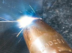
You'll always get some spatter with most GMAW applications, but to reduce spatter buildup on gun components you can use jelly or spray. Spray is convenient and fast, and sometimes used more to reduce spatter sticking to the base metal, especially when using short-circuit transfer (see Figure 1).
Jelly is cheap and lasts forever, if used properly. Try not to stick the nozzle in cold; otherwise, the jelly tends to clump up inside the gun. Instead, run a few test beads to heat up the gun components, and then dip the nozzle in the jelly.
The gun is the "business end" of GMAW, where the arcing process occurs. So before a shift, take the nozzle off and check it for spatter, especially if the welder working the prior shift was welding out-of-position. Spatter can lodge itself between the diffuser and nozzle, and the arc can actually melt the diffuser, turning a small issue into a big problem. Also, ensure the insulator is in the proper location and not covering the diffuser holes (see Figure 2).
Dents or chips in the nozzle are likely from people banging the side of the nozzle against the worktable to remove spatter--not good for the gun components and nozzle, especially a gooseneck gun. Those nozzle dents may even cause weld problems, because they can alter the delivery of your shielding gas. Your weld pool may change slightly and cause weld issues.
Instead, try removing spatter with a rat-tail file, as long as the nozzle and insulator are separate pieces. If the nozzle and insulator are one piece, a rat-tail file can ruin the threads. So in this case, try using welpers--a specialized tool that's especially helpful in GMAW and flux-cored arc welding (FCAW). The welpers' ends are square, so you can stick them into the nozzle, give them a turn, and effectively clean out your nozzle. Welpers also have notched openings designed for easy gripping of contact tips and nozzles, which help when it comes time to inspect, maintain, or replace these components.
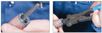
Figure 2 A small rat-tail file works for removing spatter (left) only when the nozzle and insulator are separate pieces. Welpers (right) are a good alternative for cleaning the nozzle, especially if the nozzle and insulator are one piece.
Make sure the cable isn't wrapped tightly or kinked, which can put excessive wear on or damage your liner. Also, welding cables in general can really get out of hand, particularly in multiprocess workcells. Cables strewn all over a floor coated in steel dust can create a serious tripping hazard. Use the cables you need and organize the rest. Some shops even put welding cables and wire feeds on booms, to clear floor space and improve welder access to large workpieces (see Figure 4).
Check for correct drive roll tension. Small systems usually have a single set of drive rolls that push the wire into the gun cable; larger machines have dual drive roll systems with two sets of rollers in line with each other. Some systems use a feed in which rolls mounted in the gun pull wire through the gun cable. Still others use a push-pull system, handy for aluminum or other soft wire grades (see Figure 6).
Regardless of the type of feeder, wire tension matters. If the tension is set too low, the wire can slip, leading to an intermittent welding arc. If the wire is too tight, the wire can be gouged or flattened, which can cause feeding clearance issues through the contact tip. If contact tips are wearing out quickly, check the drive roll tension, especially if you're using ribbed or grooved rollers.
Safety first. Make sure your cylinder is chained before the regulator is installed. Ensure tight connections to prevent gas leakage. Also, make sure the cylinder isn't positioned against a metallic structure (like a metal worktable) that could put it in an electrical circuit.
Check the flowmeter to ensure it has the proper CFH (cubic feet per hour). An inexperienced welder might think "more is better," but this isn't the case. You want to have enough to shield the pool but not too much, or you'll waste gas and create turbulence that distorts or even aspirates air into the molten metal in the weld pool.
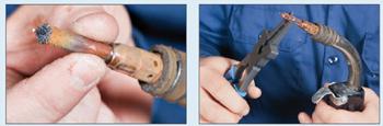
Figure 3 The worn, spatter-filled contact tip on the left should be replaced (at right) with a new contact tip that's the correct size for the wire being used.
The higher the voltage and larger wire you use, the more CFH you need. So if you are using pulse or spray transfer with a 0.052-in. wire, 40 to 45 CFH may suffice. For a short-circuit, smaller-wire application, anywhere between 25 and 35 CFH is often just fine. Of course, exact settings depend on the gas mixture, stickout, nozzle diameter, and other factors.
If the previous shift involved jobs with different base metals or thicknesses, the machine settings may have been changed. Don't just turn on the machine and assume that it's set at the correct voltage and wire feed speed for your job.
Also, consider the age of the welding machine. An older, well-used machine set at 20 volts and 190 IPM may work well, but if you move to a newer (and more accurate) machine, those same settings may cause some weld problems.
Todd Bridigum is a welding instructor at Minneapolis Community and Technical College, 1501 Hennepin Ave. S., Minneapolis, MN 55403. He is also author of How To Weld, published by MBI Publishing Co. and available at major booksellers, including Amazon.com, as well as through the American Welding Society, www.aws.org. Photos, taken by Monte Swann, are from How To Weld and are reprinted with permission.

The Fabricator is North America's leading magazine for the metal forming and fabricating industry. The magazine delivers the news, technical articles, and case histories that enable fabricators to do their jobs more efficiently. The Fabricator has served the industry since 1970.
start your free subscription
Easily access valuable industry resources now with full access to the digital edition of The Fabricator.

Easily access valuable industry resources now with full access to the digital edition of The Welder.

Easily access valuable industry resources now with full access to the digital edition of The Tube and Pipe Journal.

Easily access valuable industry resources now with full access to the digital edition of The Fabricator en Español.
In this episode of The Fabricator Podcast, Caleb Chamberlain, co-founder and CEO of OSH Cut, discusses his company’s...


