Projection welding 101
Process basics and projection design
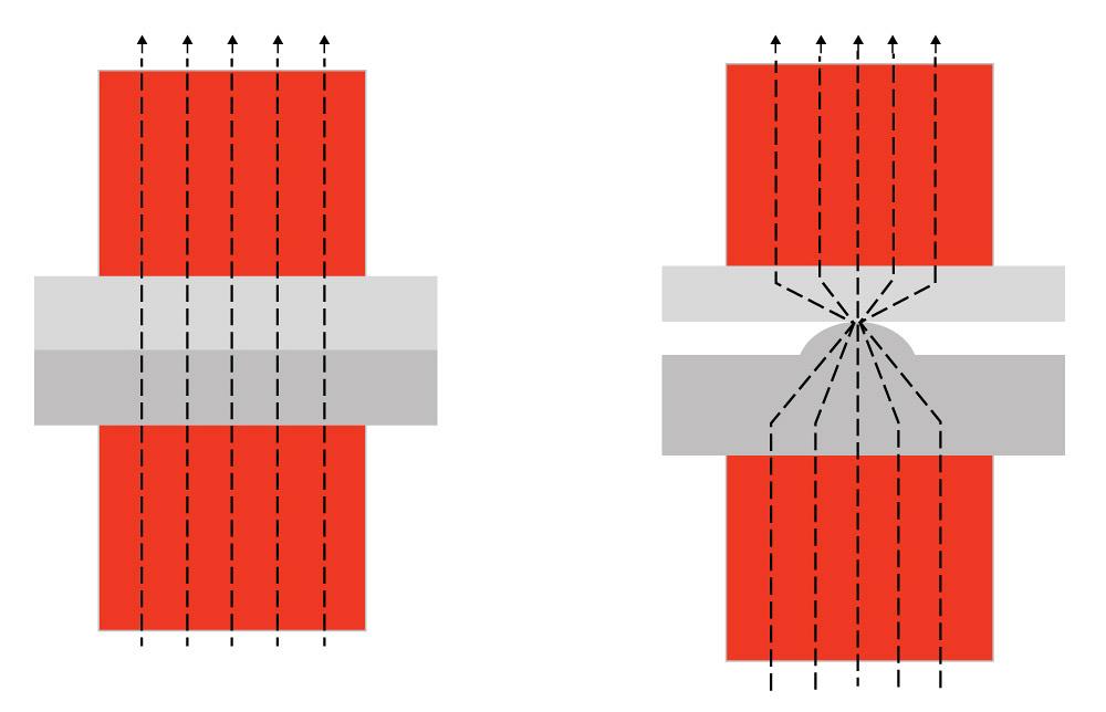
Figure 1
A typical resistance weld between two flat sheets (left) is compared to a projection weld (right). The dashed lines show the flow of welding current.
Coined or machined projections do not cause the same concerns as a stamped projection, as there is no risk of premature projection collapse during welding. The shape and size of coined or machined projections are unlimited, but a dome shape with a diameter-to-height ratio of 3-to-1 is a good starting point. Coined projections are common on welding nuts, while machined projections often are used to make circumferential projections to form a hermetic seal.
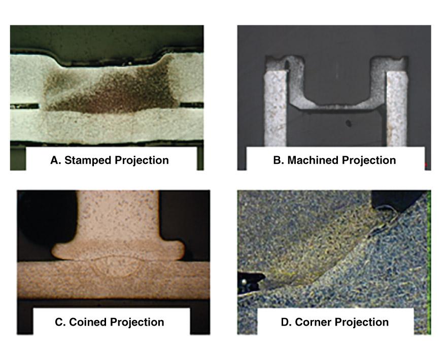
A fourth projection design is the corner projection, commonly used to plug a hole in a reservoir. Weld sections of typical projection welds are shown in Figure 3.
Strength of a projection weld can be calculated to a simple approximation by area of the dimple and assuming base metal properties for shear/tensile strength, based on type of loading during testing. The actual weld strength depends on such factors as failure mode; changes in material properties during welding; and size of the weld produced, which can be greater or less than the dimple diameter based on process parameters.
Process Control
Once the part is ready for welding at the machine, the three main factors that can be tweaked are the force, power, and time.
Force should be set so it is just enough to make a small indent at the tip of the projection before the weld is fired. Force typically is held constant throughout the weld but can be increased in the latter part of the weld to provide a forging action. Depending on the size and type of materials being welded, time can range from a few milliseconds to 1 second (50/60 cycles).
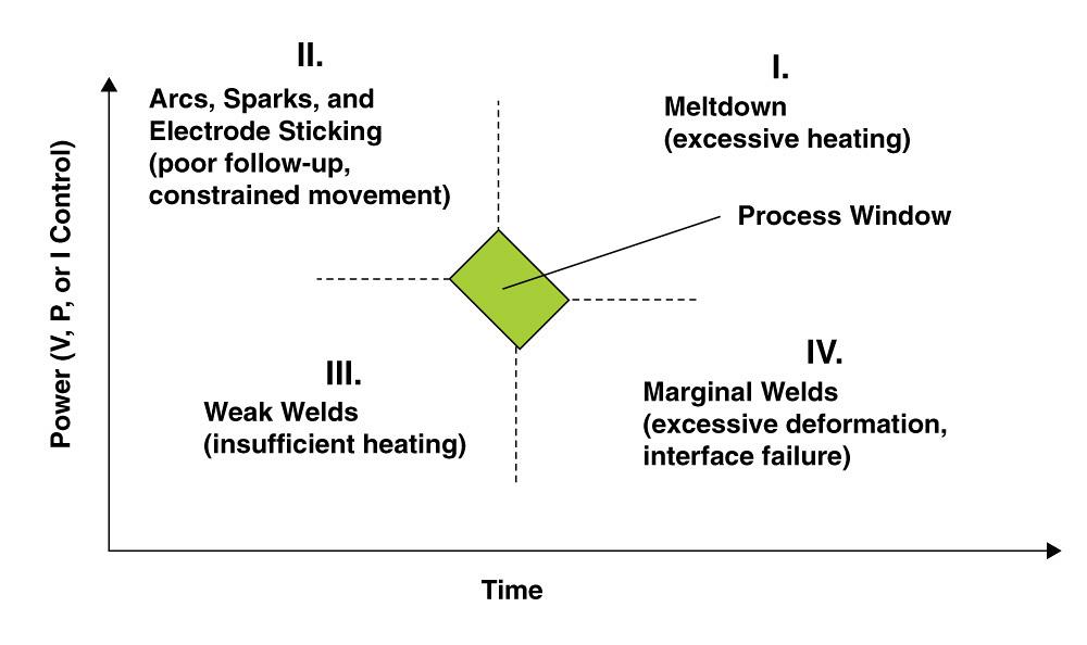
The relationship of power and time is shown in Figure 4. At low power and short time (quadrant III), welds will be weak. High power and long time (quadrant I) will deliver excessive heating and subsequent meltdown. Most active welding and process tweaking is done in quadrants II and IV.
In quadrant II, the delivery of high power in a short time can lead to arcs, sparks, and electrode sticking. Such arcing can be attributed to poor follow-up of the weld head and/or constrained movement of the parts being welded. The part in contact with the moving electrode should be completely free to move along with the electrode during weld collapse. In automated manufacturing operations, it is common to have the other end of the part anchored in a housing or fixture. Constrained movement will shrink the size of the process window.
In quadrant IV, the situation is the opposite; the weld head has good follow-up, but the power supply may not be able to deliver power fast enough, leading to a slow collapse of the projection. Longer weld time allows the weld heat to dissipate, it and prevents the weld interface from reaching the desired peak temperature, leading to weak welds.
The total energy (Energy = Power x Time) may be the same for a welding process point in quadrant II and IV, but it is the rate of energy delivery that is critical for projection welding. The process window size can be increased by proper selection of materials (electrodes and parts), part design, welding equipment, and process parameters. A wider process window allows for a robust process that is not sensitive to normal variations in incoming parts.
Other Factors
Electrode Life. With projection welding, weld size is not tied to electrode size. Consequently, the electrode size (contact area) can be much bigger than the projection size, resulting in reduced contact pressure and current density at the electrode/part interface. This reduction in pressure and current density helps increase electrode life.
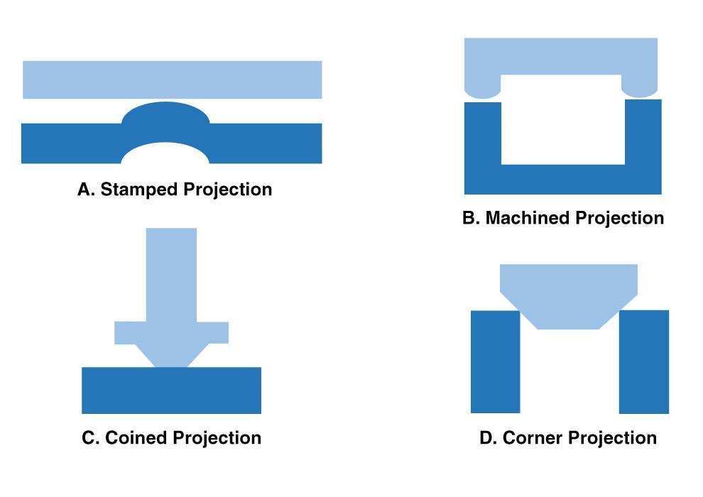
Figure 2
The four types of projection welds are shown here in schematic form. Machined and
corner projections are common in applications for circumferential welds leading to a hermetic joint.
Heat Balance. One of the challenges in welding parts that are dissimilar in size or material property is heat balance—the ability to produce equivalent softening and heating on both sides of the weld interface. If the parts being welded are considerably different in size (thermal mass) or material properties (melting point, conductivity), welding with conventional resistance welding can become difficult. In such situations, a projection on the larger or more conductive part helps regain heat balance.
Removal of Plating. A key attribute of projection welding is the ability to get rid of plating on the surface and expose parent metal on both sides for a direct bond. Plating material often interferes with welding; for example, zinc plating on the surface of galvanized steel is not conducive to welding because it has poor bond strength and can actually form cracks in the weld by weakening the grain boundaries.
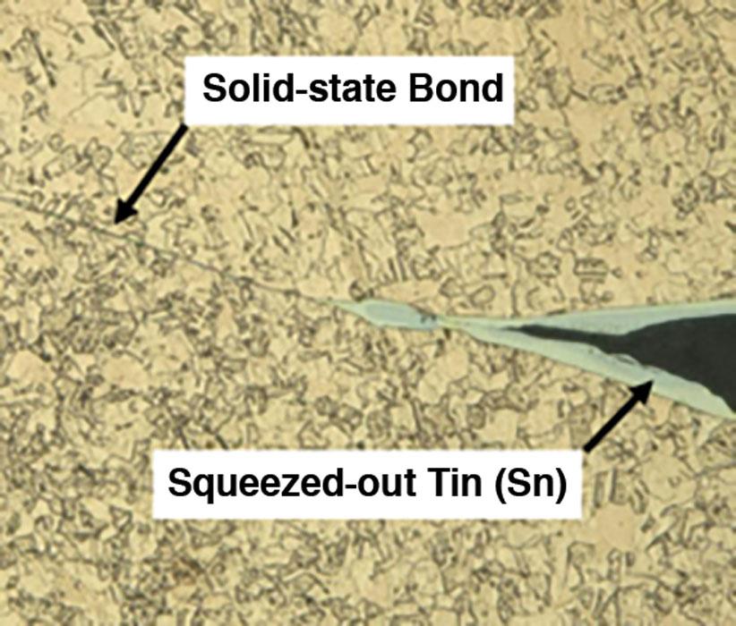
When welded with projection welding, most of the zinc plating gets flashed out during the early part of the weld cycle. The results when welding tin-plated copper parts are similar: Tin plating is squeezed out and allows base copper on both sides to come in contact and form a strong copper-copper, solid-state bond (see Figure 5). The plating should have a lower melting point than the base alloy.
Multiple Spot Welds. Projection welding is a good option when multiple spot welds have to be made in reasonably close proximity at predetermined locations. It is a straightforward process, and all the welds can be made with a single electrode.
About the Author
About the Publication
subscribe now

The Welder, formerly known as Practical Welding Today, is a showcase of the real people who make the products we use and work with every day. This magazine has served the welding community in North America well for more than 20 years.
start your free subscription- Stay connected from anywhere

Easily access valuable industry resources now with full access to the digital edition of The Fabricator.

Easily access valuable industry resources now with full access to the digital edition of The Welder.

Easily access valuable industry resources now with full access to the digital edition of The Tube and Pipe Journal.

Easily access valuable industry resources now with full access to the digital edition of The Fabricator en Español.
- Podcasting

In this episode of The Fabricator Podcast, Caleb Chamberlain, co-founder and CEO of OSH Cut, discusses his company’s...
- Trending Articles
1
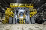
Sheffield Forgemasters makes global leap in welding technology

2
Welding student from Utah to represent the U.S. at WorldSkills 2024

3
Lincoln Electric announces executive appointments

4
Lincoln Electric acquires RedViking
5
Engine-driven welding machines include integrated air compressors