Applications Welding Engineer
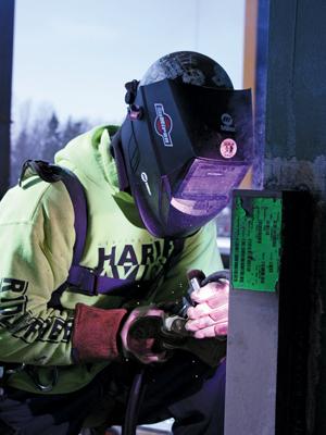
As contractors in the structural steel industry look for ways to boost productivity and efficiency in an increasingly competitive environment, some are making the switch from shielded metal arc welding (SMAW) to self-shielded flux-cored arc welding (FCAW) as one way to gain an edge.
For many years contractors have relied heavily on SMAW to complete most of the on-site fabrication for major infrastructure jobs, mostly because it is familiar to many welders, it has mobility advantages over other processes, and it also is often specified by the welding procedure for many construction applications.
However, in recent years self-shielded FCAW has improved the way some welding contractors do business. The process is faster, increasing productivity and providing greater cost savings. If you are considering making the change to self-shielded FCAW because of these advantages, remember to also consider the proactive measures you’ll need to take to make that transition successful. It’s important to have a solid understanding of the characteristics and operating requirements of the new filler metal being used to weld successfully with it.
The first thing to remember is that whether you are fabricating components for erecting structural steel or constructing portions of a bridge, strict codes regulate the procedure, the materials, and the filler metal that you can use. For example, the American Welding Society (AWS) D1.1 structural welding code and AWS D1.5 bridge welding code dictate the base metal and filler metal combination for these applications, along with the power supplies.
Under these specifications, a self-shielded flux-cored wire that meets the AWS E71T-8 classification is a common requirement for structural steel applications and one that can be advantageous if you’re looking to convert from a SMAW electrode. Also known in various industries as a T-8 wire, this wire, like any filler metal, requires proper technique and training to achieve optimal results.
When the job requires welding to either of these codes and the change is made to a T-8 wire, you will need to requalify welding procedures, as well as your company’s welding operator certifications, to make the change in welding processes. These tasks may seem burdensome, but you need to have your certifications requalified periodically anyway. Ultimately, it’s a change that could result in a faster, easier process.
The second thing to remember when considering a switch to self-shielded FCAW is the need for proper equipment. This is absolutely critical to weld to code. When using a T-8 wire, you’ll need a constant-voltage (CV) power source.
While some contractors may want to save on the cost of the equipment purchase by adding a voltage-sensing feeder to a constant-current (CC) power source that is already used for their SMAW process, this system is not acceptable for self-shielded flux-cored welding to AWS code D1.1. That’s because it doesn’t react quickly enough to maintain a steady voltage throughout the welding process. That can lead to weld defects, especially porosity, which can end up costing more money in downtime, rework, and possibly contract fees than the upfront cost of a new CV power source.
The third consideration in making a transition from SMAW to a self-shielded FCAW process is finding the specific type of self-shielded flux-cored wire that is best-suited for the application. As mentioned earlier, a T-8 wire is typically the self-shielded flux-cored wire used for structural steel applications. A number of options meet seismic requirements and offer the necessary high impact strengths for critical code work. A filler metal manufacturer or trusted welding distributer can help you make the best selection.
The key to using a T-8 wire, in addition to getting the necessary training and practice, is a general understanding of its characteristics and operating requirements, and knowledge of how its chemical and mechanical properties are designed to meet the needs of critical structural steel applications.
Classified for Performance. Being familiar the various portions of its AWS classification is a good first step in becoming comfortable with a T-8 self-shielded flux-cored wire, beginning with its most basic arrangement, E71T-8:
Due to advances in filler metal manufacturing technology, some T-8 wire also offers additional designations for impact strength, seismic requirements, and hydrogen content; all are factors that contribute to the suitability and usability of a T-8 wire for a specific application.
For example, the addition of the letter “J” to the end of the AWS classification indicates the wire offers high “as-welded” impact strength properties at -40 degrees F. A “D” after that indicates the wire can be used for demand-critical welds in special seismic applications. Finally, the presence of “H8” or another, similar alphanumeric indicator at the end of the AWS classification specifies the amount of diffusible hydrogen in that T-8 wire.
Understand Wire Parameters. If a contractor makes the change to self-shielded FCAW, welding operators should know the general characteristics and operating requirements of T-8 wire to achieve the best weld possible, along with the X-ray quality required for critical applications. Training is important for the conversion to be successful.
Fluctuations in voltage are common on many job sites and they affect the performance of T-8 wires. The length and condition of welding leads can cause voltage drops between the power source and the workpiece, and that is especially true with long welding leads. Using a multimeter or a wire feeder with digital voltage meters can help you maintain the proper voltage range. Maintaining good weld cable conditions and secure connections between the welding gun and the power source also helps.
The allowable voltage ranges for T-8 wire vary according to the filler metal manufacturer’s formula; the position in which it is used; and, most important, the wire feed speed, which directly affects amperage. Generally, T-8 wire operates at 200 amps or greater, with a voltage range from 18 to 24 V on an all-position weld regardless of wire diameter. For this reason, you should always weld within those parameters to avoid defects that could lead to time-consuming and costly rework.
Another issue to be aware of is excessive voltage—voltage beyond the highest recommendation for the T-8 wire—which can cause discontinuities such as porosity and worm-tracking. Conversely, not enough voltage can prevent the wire from wetting out properly and lead to cold roll, both problems that can result in weld inspection failure.
Maintaining the welding parameters of a T-8 wire also depends on electrode extension, or stickout, and this varies according to the filler metal manufacturer. As a rule, most T-8 wire requires a range of ¾ to 1¼ inch of stickout, depending on the diameter used. The general rule is that a small-diameter wire will require a shorter stickout than a large-diameter wire.
Stickout that is too short causes the amperage to increase disproportionately to the voltage setting, which can lead to a lack of fusion. Stickout that is too long will cause the amperage to be too low for the given voltage setting, leading to incomplete slag coverage and, ultimately, any number of weld discontinuities. To help minimize these problems, always check the specific stickout requirements for the T-8 wire being used.
Finally, T-8 wire requires an appropriate gun angle and travel speed to prevent slag inclusions. Gun angle varies from wire to wire, from 10 to 45 degrees; you should always follow the manufacturer’s recommendations. As a rule, the presence of a uniform slag line behind the weld puddle is a good indicator that both proper gun angle and travel speed requirements have been met.

The Welder, formerly known as Practical Welding Today, is a showcase of the real people who make the products we use and work with every day. This magazine has served the welding community in North America well for more than 20 years.
start your free subscription
Easily access valuable industry resources now with full access to the digital edition of The Fabricator.

Easily access valuable industry resources now with full access to the digital edition of The Welder.

Easily access valuable industry resources now with full access to the digital edition of The Tube and Pipe Journal.

Easily access valuable industry resources now with full access to the digital edition of The Fabricator en Español.
In this episode of The Fabricator Podcast, Caleb Chamberlain, co-founder and CEO of OSH Cut, discusses his company’s...