


Understanding the connection: Welding equipment and filler metals
Matching your filler metal type and size with the capabilities of your welding equipment and the needs of your application can help you avoid poor wire feeding, weld defects, or costly rework.
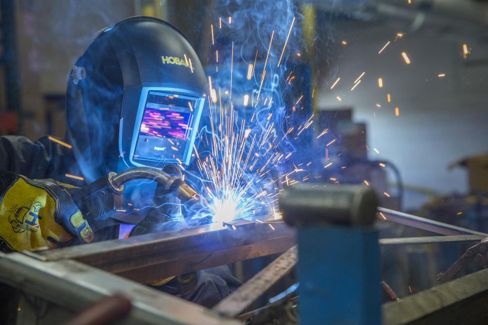
Many factors contribute to high-quality welds, from using proper welding techniques to choosing the right equipment, consumables, and filler metals.
Matching your filler metal type and size with the capabilities of your welding equipment and the needs of your application are additional considerations that can help you avoid poor wire feeding, weld defects, or costly rework. If your equipment doesn’t have the capacity to operate a given wire size, for example, you may experience lack of weld penetration and poor weld quality. Or if the filler metal isn’t appropriate for the base material, you may see problems with porosity or other weld inconsistencies.
Consider these three questions to guide your selections.
1: What Is Your Welding Application?
Determine what you’re trying to accomplish before deciding which filler metal and equipment combination will get the job done. Base material type, welding position, and joint configuration affect the selection.
Some welding equipment and processes can be used to weld certain materials only. For instance, gas tungsten arc welding (GTAW) of aluminum generally requires an alternating current-capable power source. Your base material affects your filler metal options, too. Select a product based on how well it matches the mechanical and chemical properties of the material.
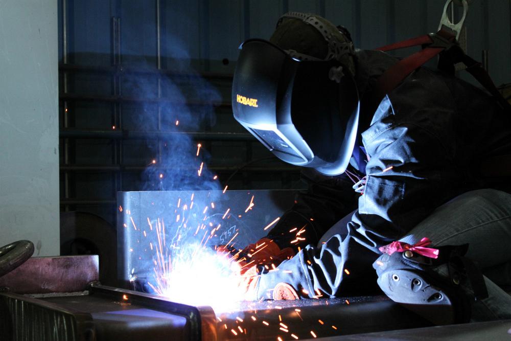
Welding position also plays a role in your success. Larger-diameter welding wires offering higher deposition rates can typically be used for flat or horizontal welding. Vertical or overhead welds typically require smaller-diameter wires with lower deposition rates, which are more forgiving in out-of-position welding.
Next, understand what type of joint you are welding. An open-root, V-groove joint on a pipe requires a different procedure and equipment than a high-speed, robotically welded application, for example. Some machines also are better suited to certain joint configurations than others, depending on the power required.
2: What Is Your Welding Equipment Capable of?
Once you’ve determined your filler metal and equipment needs based on your application, consider the capabilities of your welding equipment. Can it meet the demands of the job?
First, assess the duty cycle and maximum output of your welding power source. Both help determine which applications the machine can handle. The thicker the material, the more output or current your power source must generally produce to create quality welds. Smaller, lighter-duty machines may simply not have the power output to offer appropriate joint penetration on a thicker piece of material. To guide the selection, welding equipment manufacturers typically provide estimates on the thickness of material their specific power source can weld. Some newer power source models provide preset welding parameters based on material thickness ranges.
Also consider additional factors and components in your welding system — the shielding gas, the gas metal-arc welding (GMAW) gun, and consumables, as well as drive rolls and guides, the ground cable, and available input power. These should all match the needs of the filler metal type and size required for your application. For instance, if your power source can run a 0.045-inch welding wire, match your tips and liners to this same diameter. Be certain that your drive rolls and guides are similar diameter and appropriate for the type of filler metal — V-knurled drive rolls for gas- and self-shielded flux-cored wire and metal-cored wires, V-groove drive rolls for solid wire, and U-groove drive rolls for aluminum or other soft wires.
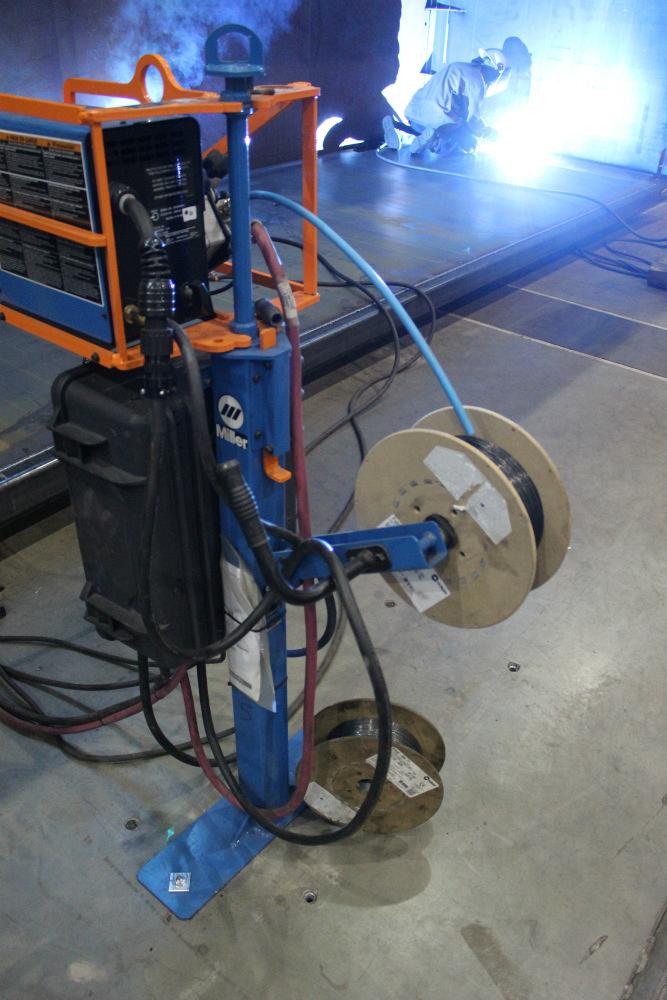
For the best results, assess the duty cycle and maximum output of your welding power source. Both help determine which applications your power source can handle.
3: What Type of Filler Metal Will Work?
When choosing your filler metal, consider the manufacturer’s recommended parameters for the product and assess how those parameters match your power source capabilities.
Solid, flux-cored arc welding (FCAW) wires and metal-cored wires can be used, in common wire sizes, for different welding processes and materials. Here are a few typical examples.
- Short-circuit transfer on sheet metal and thin material using solid wire: 0.023- to 0.035-in.-diameter wires.
- Globular transfer on thin to medium thickness materials with solid wire: 0.035- to 0.045-in.-dia. wires.
- Spray transfer on medium to thick material with solid wire: 0.045- to 0.062-in.-dia. wires.
- Pulsed welding on thin to thick material with solid wire: 0.035- to 0.062-in.-dia. wires.
- Globular transfer on thin to thick material with FCAW wire: 0.035-inch to 1/16-in.-dia. wires.
- Spray or pulsed spray transfer on thin to thick material with high deposition using metal-cored wire: 0.045- to 0.062-in.-dia. wires.
The filler metal and process you use will affect the characteristics of the completed weld, including strength and appearance.
Producing High-quality Welds
To produce high-quality welds, be sure you answer the three key questions in this article. If you have questions regarding the type or size of filler metal to select for your welding equipment — or questions regarding your power source capabilities — consult filler metal spec sheets or contact your filler metal manufacturer for recommendations. You can also consult with a trusted distributor. These resources often can provide a recommended range of operating parameters for specific applications to ensure your welding power source and filler metal can tackle the job.
When choosing your filler metal, consider the manufacturer’s recommended parameters for the product and assess how those parameters match your power source capabilities.
About the Author
About the Publication

subscribe now

The Fabricator is North America's leading magazine for the metal forming and fabricating industry. The magazine delivers the news, technical articles, and case histories that enable fabricators to do their jobs more efficiently. The Fabricator has served the industry since 1970.
start your free subscription- Stay connected from anywhere

Easily access valuable industry resources now with full access to the digital edition of The Fabricator.

Easily access valuable industry resources now with full access to the digital edition of The Welder.

Easily access valuable industry resources now with full access to the digital edition of The Tube and Pipe Journal.

Easily access valuable industry resources now with full access to the digital edition of The Fabricator en Español.
- Podcasting

In this episode of The Fabricator Podcast, Caleb Chamberlain, co-founder and CEO of OSH Cut, discusses his company’s...
- Trending Articles
1
AI, machine learning, and the future of metal fabrication

2
Employee ownership: The best way to ensure engagement

3
Steel industry reacts to Nucor’s new weekly published HRC price

4
How to set a press brake backgauge manually

5
Capturing, recording equipment inspection data for FMEA
