Keishi Taki
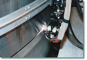 |
| The new shroud was welded with narrow-gap GTAW. The groove in this shroud was open by 6 degrees and 0.28 in. (7 mm) wide at the parallel section. |
This process allows uniform welding with first-layer penetration in all positions. The wire feed and base metal fusion rates can be controlled independently, allowing the operator to select from a range of welding parameters. It delivers a high-quality joint with minimal slag because inert gas is used for shielding. However, efficiency is low, as is penetration into groove walls, and torch position must be accurate.
Efforts are being made to improve efficiency by combining high-deposition techniques, such as hot- or double-wire, and deep-penetration techniques, such as double-shield nozzles, with narrow-gap GTAW. Another effort to increase penetration into groove walls is to combine oscillation and high-frequency pulse current techniques with narrow-gap GTAW methods.
Hot-wire Method. In this most popular narrow-gap GTAW technique, electric currents passing through filler wires increase the deposition rate. The amount of electric current that can be used is limited because of the arc blow that results. A switching method has been developed to flow arc and wire current alternately to solve this problem.
In another hot-wire method, the welding wire is inserted from behind the weld pool, and a small direct current flows through the wire. This causes the GTAW arc to incline in the weld advancing direction.
Double-shield System. This method is used to supply center and shield gas. The center gas cools the arc column to converge the arc, increasing the electric current density. A typical application uses mixed gas of 50 percent helium and 50 percent argon as the center gas and argon gas outside the mixed gas. This successfully increases the depth of penetration.
Combining this approach with a hot-wire method or a twin-wire method, in which a wire is inserted from behind, also increases the deposition rate.
Oscillation Method. In this method, a tungsten electrode is mounted at a slant on the torch shaft while the shaft is twisted to increase penetration into the groove walls. Arc oscillation prevents formation of voids that normally are generated by a high-current arc.
Combining the oscillation method with the hot-wire method can result in high-speed, high-deposition welding. The actual realized deposition rate typically is 60 grams per minute in flat position and 35 grams per minute in vertical-up position.
 |
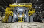
| Figure 1 This cylindrical pressure vessel, or shroud, was narrow-gap-welded with minimal heat input to the existing shroud supports. |
Other Techniques. GTAW also can be used with the maximum peak current of 500 amps at high-frequency pulses of 5 to 15 kilohertz to help improve the arc's concentration on the center of the groove.
Another technique is the two-electrode method, in which a torch with two electrodes generates two arcs simultaneously. The pulses are overlapped on each electrode to produce large currents without concentration of arc force. The maximum deposition rate is 30 grams per minute.
Nuclear Power Pressure Vessel. To improve the reliability of nuclear power stations and to prevent stress corrosion cracking, Toshiba manufactured a shroud, a large internal component in the reactor, with a new material to replace the existing one after core shroud cracking was discovered in 1990. Narrow-gap GTAW was used for the on-site welding.
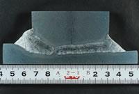 |
| Figure 2 This cross-sectional macro shows the welded SUS316L shroud. |
Figure 1is an external view of the shroud. This cylindrical pressure vessel is about 22.97 feet (7 meters) high and weighs about 34 tons. Narrow-gap welding with minimal heat input was used to weld the shroud to the existing shroud supports.
Narrow-gap GTAW also was used in the shop manufacture of the new shrouds. Figure 2shows the cross-sectional macro structure of the welded SUS316L shroud. The introductory photoshows the weld being made. The groove was open by 6 degrees and 0.28 inch (7 millimeters) wide at the parallel section.
The single-wire (cold-wire), double-gas shield method was used as the narrow-groove GTAW technique. An argon and hydrogen mix was used as the center gas, and argon with 50 percent helium was the shield gas. Pulse welding was used to weld the 1.69-in. (43-mm) length with about 21 passes at a welding speed of 5.51 inches per minute (IPM) (140 mm per minute).
 |
| Figure 3 Double-shield hot-wire and oscillating narrow-gap GTAW were used for the external and internal wall welds, respectively, of this vacuum vessel sector, a double-wall, 18-degree split model. |
Nuclear Fusion Equipment. Narrow-gap GTAW was used in the manufacture of the actual-size SUS316LN model of a vacuum vessel for the International Thermonuclear Fusion Experimental Reactor as part of the International Thermonuclear Fusion Experimental Reactor Engineering Design Activity in Japan, which began in 1992. The vacuum vessel sector model (see Figure 3), a double-wall, 18-degree split model, is 29.53 ft. (9 m) wide and 49.21 ft. (15 m) high. Double-shield hot-wire and oscillating narrow-gap GTAW methods were used for the external and internal wall welds, respectively.
The remote-controlled automatic welding unit features a nine-axis welding vehicle that travels on rails installed on the internal walls. The arm is inserted at 7.09-in. (180-mm) intervals, and the welding head remains no farther than 33.86 in. (860 mm) away. The double-shield hot-wire method used for this application achieved the maximum deposition rate of about 42 grams per minute in the vertical position. A high deposition rate of 30 grams per minute was achieved on average in all-position welding.
|
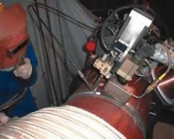
| Figure 4 Narrow-gap hot-wire GTAW is used for on-site welding in a thermal power plant. |
Piping. A typical thermal, nuclear, or other power plant can contain more than 70,000 pipe joints. Pipe sizes can range from as large as 35.43 in. (900 mm) OD and 3.15 in. (80 mm) wall to as small as 0.79 in. (20 mm). Narrow-gap GTAW typically is used on pipes with walls 1.57 in. (40 mm) and thicker. Figure 4shows narrow-gap hot-wire GTAW in a thermal power plant.
Boiler Header. When narrow-gap hot-wire GTAW is used for boiler header end plates, the header is rotated to weld two locations simultaneously on the circumference. A CCD camera is installed on the welding head to monitor the welding process. The applicable materials are carbon steels, low-alloy steels, and 9Cr steels.
Generator Rotor. Narrow-gap GTAW was used in developing a superconducting generator winding shaft (see Figure 5) made of INCONEL 706 alloy. Since integral forging was impossible, the parts—27.56 in. (700 mm) OD, 78.74 in. (2,000 mm) long, and 9.84 in. (250 mm) thick-were integrated into a single unit by welding. Narrow-gap GTAW was used because of the necessity to restrict welding deformation and to ensure welding efficiency.
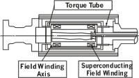 |
| Figure 5 Narrow-gap GTAW was used in developing a superconducting generator winding shaft made of INCONEL® 706 alloy. This process was used because it was necessary to restrict welding deformation and to ensure welding efficiency. |
MC-TIL narrow-gap welding equipment from Kobe Steel Ltd., Japan, was selected to deflect the arc toward the groove walls in the magnetic field of the coil.
Steam Turbine Rotor. Narrow-gap hot-wire GTAW was applied to join chromium-molybdenum-vanadium to nickel-chromium-molybdenum-vanadium forgings to create a turbine rotor in which high- and intermediate-pressure parts were welded to a low-pressure part (see Figure 6).
A large, full-scale prototype was welded to demonstrate that the weld could be made successfully in production. The prototype rotor was 19.69 ft. (6 m) long and about 27.56 in. (700 mm) OD. Wall thickness of the weld was 5.91 in. (150 mm), and groove width was 0.28 in. (7 mm).
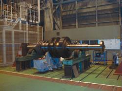 |
| Figure 6 This turbine rotor was made using narrow-gap hot-wire GTAW. A large, full-scale prototype was welded to demonstrate that the weld could be made successfully in production. |
One of the important tasks of narrow-gap GTAW is to improve efficiency. Many techniques have been proposed and commercialized to increase deposition rate. Narrow-gap GTAW requires accurate seam tracking because the grooves are narrow. Torch position and welding conditions must be controlled adaptively to prevent incomplete fusion on the groove walls.
It also requires high precision because of low penetration into groove walls. For thick plates, the position of the torch tip is difficult to identify, so the operator must have a high level of control.
A functional automatic welding system with a visual sensor was developed and commercialized to meet these requirements.
In shop production, however, the welding process must be performed with as little manual intervention as possible for cost reduction.
An automatic, monitorless narrow-gap hot wire GTAW unit for pipes has a CCD camera and a laser sensor on the welding head. Before welding starts, the laser sensor measures the shape of the groove to teach the welding line and establish welding conditions.
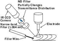 |
| Figure 7 A special multiple filtering system with a filter of partially variable transmittance was developed for this CCD camera. The camera processes images of the weld pool and its periphery, automatically corrects the positions of the electrode, and adaptively controls welding conditions. |
During welding, the images of the weld pool and its periphery taken by the CCD camera are processed, the positions of the electrode and wire automatically are corrected, and the welding conditions are controlled adaptively. Another function of the system measures the bead shape after welding to detect undercut, unevenness, and wetting angle errors automatically. For this unit, a special multiple filtering system has been developed (see Figure 7).
Satoru Asai is chief specialist, Production Engineering; Keishi Taki is group manager, Material Processing; and Tsuyoshi Ogawa is an engineer, Material Processing, Keihin Product Operations, Power Systems & Services Co., Toshiba Corporation, 2-4, Suehiro-cho, Tsurumi-ku, Yokohama 230-0045, Japan, +81-(0)45-510-5380, fax +81-(0)45-500-1401, satoru.asai@toshiba.co.jp, keishi.taki@toshiba.co.jp, tsuyoshi.ogawa@toshiba.co.jp, www.toshiba.co.jp. Power Systems & Services Co. is a division of Toshiba Corp. The company manufactures power generation equipment for thermal power, hydraulic power, and nuclear power systems and supplies the service to electricity utilities.
INCONEL is a registered trademark of the Special Metals group of companies.

The Welder, formerly known as Practical Welding Today, is a showcase of the real people who make the products we use and work with every day. This magazine has served the welding community in North America well for more than 20 years.
start your free subscription
Easily access valuable industry resources now with full access to the digital edition of The Fabricator.

Easily access valuable industry resources now with full access to the digital edition of The Welder.

Easily access valuable industry resources now with full access to the digital edition of The Tube and Pipe Journal.

Easily access valuable industry resources now with full access to the digital edition of The Fabricator en Español.
In this episode of The Fabricator Podcast, Caleb Chamberlain, co-founder and CEO of OSH Cut, discusses his company’s...