


AWS CWI, CWE, NDE Level III
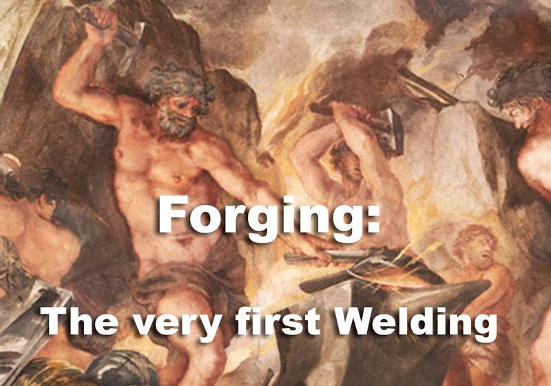
Figure 1
Vulcan’s Forge painting from the Allegory of Divine Providence by Pietro da Cortona.
Part I of this series discussed safety and the fundamentals of teaching the oxyacetylene process. Part II addresses some of the many uses and techniques of the process that are relatively unfamiliar to much of today's welding community.
In the 1930s and 1940s the use of the oxyacetylene process was prominent. Welding shops often were not equipped with the necessary electricity to support electric arc welders. The portability of the oxyacetylene welding (OAW) equipment was far superior to that of the electric arc equipment. Much of our country was rural in those years, and only small repair shops provided welding services.
The OAW torch was more efficient than the blacksmith forge (Figure 1), and the OAW process produced a higher-quality, stronger weld than forging. By the time the metal was brought up to heat in the forge, the OAW process could complete the weld.
Few types of metal were available in those years, and the alloys in the filler metals were very limited. One of the most popular rods then, and even now, was the bronze alloy RBCuZn. The bronze rod opened up a new adventure. At last cast iron could be repaired by welding.
Of course, then and now, some types of cast iron are not weldable. Gray cast is one of them. This is a copper/zinc alloy that was used with a flux similar to Boraxo® or 20 Mule Team® cleaning powder. Many old-timers created their own fluxing agents from ground-up soap and even ground light bulbs to add silicon.
The rod was dipped into the flux while it was still hot. To make sure that the flux covered the weld area, the welder moved the flame in a circular motion to stir the puddle.
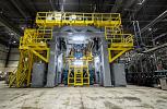
For many years, walk-behind Gravely® Tractor gasoline tanks were welded with oxyacetylene. The parts were designed specifically for this process. The rolled 16-ga. sheet was placed in a positioner, and the preformed end cap was placed inside the rolled sheet to facilitate a continuous autogenous weld efficiently. This was Gravely's first automation project (Figure 2).
Several techniques can be used with the OAW process. All techniques described in this section should be performed with a neutral flame.
As pointed out previously, always start with excess acetylene and bring the oxygen up slowly to achieve a soft inner cone. Too much acetylene presents a large yellow envelope. Too much oxygen produces a harsh flame that sometimes departs from the tip. It also has a tendency to blow the molten metal out of the puddle (Figure 3).
Many different types and sizes of torches are available. For welding materials 16 ga. and thinner, a small torch, often referred to as an "aircraft torch," is the preferred style. The flame sometimes must be adjusted during welding on these materials to minimize burn-through. Most aircraft torches have the adjusting valves toward the front of the torch and so can be adjusted easily. Because of the relatively low volume of gas required, these torches are equipped with small hoses (usually ¼ in. ID) that allow for easier handling and manipulation (Figure 4).
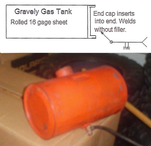
Figure 2
For many years, Gravely® walk-behind tractor gasoline tanks were welded using the oxyacetylene process.
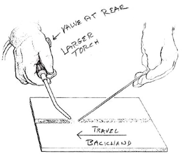
The larger torches used for welding or brazing heavier materials require a higher volume of gas and larger hoses, typically with a 3/8 in. dia. Adjusting valves usually are located toward the rear of the torch (Figure 5). The reason for the larger hoses is that starving a torch for gas can cause a backflash. Even with flash arresters, this occurrence can damage the torch and possibly the hoses and regulators.
If a whistling sound is heard, extinguish the torch immediately and close the cylinder valves. Then disconnect the torch and inspect it for damage.
If the mixer is blackened, wipe it clean with an oil-free cloth or paper towel. If the O-rings are damaged, the torch should be cleaned and repaired by a qualified torch repair technician. The hoses should be disconnected at the regulator and checked for blackening. If this is the case, the hoses can be cleaned by a professional or replaced. Regulator fittings also should be inspected. If blackening is observed, the regulators should also be serviced by a professional.
Other issues that can create a blackflash may be using the incorrect hose size, touching the tip to the work (especially into the molten puddle), or using an acetylene gas cylinder that is nearly empty.
Another critical warning is never place the acetylene cylinder in the horizontal position. Doing so allows the acetone that stabilizes the gas to creep into the regulators and sometimes even to the hose and torch. If you observe white sparks at the end of the torch, have the whole assembly serviced by a professional.
The techniques that are not taught much in the training programs today are the "forehand" and "backhand" methods (see Figure 4 and 5). This was one of the most prevalent subjects taught in the old Linde Division of Union Carbide training programs. It was fairly easy to remember that in forehand welding a right-handed welder welds right to left. Of course the opposite is true for the left-handed who welds left to right.
In forehand welding, the flame is directed toward the unfinished end of the weld. In backhanded welding the flame is directed toward the finished end of the weld. The forehand method is easier for the beginner, because the weld is more visible, especially on the first pass when the open root can be more easily observed.
When you are adding filler metal, the rod angle is just the opposite of the flame. This is true whether you are a left-handed or right-handed welder. This condition also aids visibility of the joint and the weld puddle. Proper manipulation of the torch and the filler wire is important for producing a satisfactory and aesthetically pleasing weld with nice smooth ripples.
The type and amount of manipulation depend greatly on the thickness of the material and the joint design. In any case, the filler wire and the torch should be in constant motion. The flame should move back and forth and across the joint and the filler wire.
Use larger torches and hoses with base material 3/8 in. or thicker. Direct the filler wire and the flame to the edges and across the weld. The inner cone must be directed to the wire briefly to melt the end of the wire. The back-and-forth movement is critical to ensure that the joint is being filled without voids. Too much across motion may result in a void between passes from a lack of melting of the previous pass.
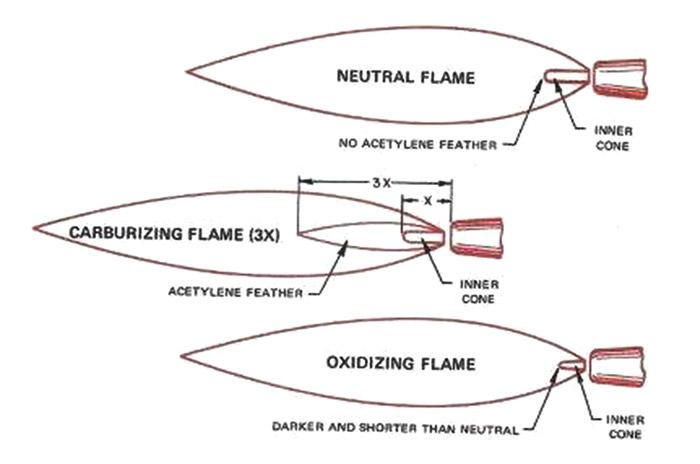
Figure 3
Oxyacetylene welding flame types.
In all cases, whether you are welding thick or thin material, place periodic tacks along the joint to prevent distortion. Because of slow heat input, the OAW process is more apt to cause distortion than the faster-heat-input processes such as gas metal arc welding (GMAW/MIG).
The smaller aircraft torch and ¼-in. hoses are best for welding thin material. If the material becomes too hot, you can adjust the torch's front-mounted valves while welding. The forehand technique is best for welding the thinner material; it produces less distortion. However, it is a good idea to switch ends occasionally (after completing about 4 in. of the weld).
It is necessary to differentiate brazing from braze welding.
Brazing. Brazing is a process in which the filler metal has a melting point above 800 degrees, but lower than the base material to be joined or overlaid. (Soldering is defined as having a melting point below this temperature.)
In brazing the filler metal is drawn into the base material by capillary action. This phenomenon is described as the ability of a liquid to rise into a gap against the force of gravity. These definitions may seem insignificant to a newcomer, but he soon learns that if the brazing filler metal is overheated, it will "pop out." Many have learned this the hard way!
In brazing the major portion of the heat is directed to the base material and only slightly to the filler metal. It is very easy to braze thin materials with the aircraft torch. This method is used in autobody repairs to tack in the replacement panels.
The most common filler used is still the RBCuZn alloy, which is almost always flux-coated these days. With the proper heat, this alloy produces a beautiful appearance. It is often used in metal art (sculpturing).
Silver brazing alloys are used for specific purposes, such as "tipping" electrical contacts. These alloys have classifications such as RBAg-1, etc. The same technique used with bronze is used with the silver alloys.
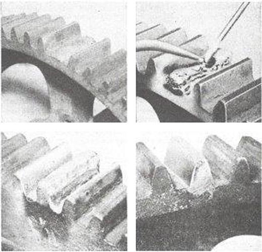
A common alloy for artwork and overlayis Allstate 13FC. This alloy can be used to form statuettes by building layers and can even be used to form limbs for artistic trees. But the most prominent use for this alloy is building up gears (Figure 6). Its tensile strength is up to 85,000 PSI. Its Brinell hardness is up to 110 as welded and 200 after work hardening. The longer the alloy is in service, the harder it becomes. It is excellent for shaping nearly any configuration. The manufacturer states that it will wear 10 to 14 times longer than steel or cast iron.
I believe it is necessary to address one more brazing alloy, even though it has no classification—aluminum with flux in the center.
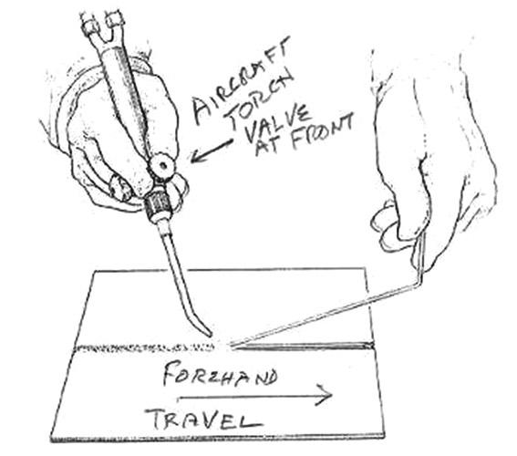
Figure 4
Using the aircraft torch with the forehand method.
This filler material is like one of the TV infomercials that can only be ordered on the show. It truly is one of a kind. It can be used to fill holes in aluminum boats and to build up marine propellers that are worn or have nicks in them. Another application is to build up the ribs on the bottoms of small aluminum fishing boats, which often are pulled out of the water onto the bank or onto a concrete landing. The scraping causes the ribs to thin. The alloy protects the ribs from wearing all the way through.
This alloy works well with all welding positions. In my dirt bike days, I used it to make clutch and brake levers. Thanks to the alloy's low melting point, I could build onto the original lever while it was still on the bike. It was easy to shape the lever, and even to add the knob on the end that was designed to prevent the hand from slipping off the lever.
If the whole rod is not expended, the end can be crimped to retain the flux and keep the moisture out. This was another use for my aircraft torch. After the brazing job is complete, the flux must be flushed with water. Polishing is an easy task, and the parts may be anodized with only a slight color change.
Braze Welding. Although the same filler material is often used in braze welding, the process differs from brazing in that the base material must be heated to about 1,600 degrees F and "tinned" before beginning the weld. The flame must be slightly oxidizing (longer, thinner inner cone).
Because of the intermixing of the filler and base materials, many dissimilar materials can be joined with braze welding. For example, copper and bronze materials may be successfully joined if the proper heat is applied with no overheating.
If the filler bubbles and spreads irregularly, the material is too hot. If the filler metal piles up on the surface, the material is not hot enough. A metallurgical bond actually forms in braze welding, even though it is microscopic.
Because it requires much greater heat than brazing, braze welding is much more difficult to control. The base metal must be hotter than the heat required for creating capillary action in brazing. The increased heat can cause porosity and distortion in the weld area.
The weld area must be completely cleaned with no rust, oil, or other contaminants for the tinning to be effective. The filler must be applied at just the right moment, and the travel speed must be at a constant level. This process is not as forgiving as the brazing process.
Part III will focus on the best uses of OAW.

AWS CWI, CWE, NDE Level III
Weld Inspection & Consulting

The Welder, formerly known as Practical Welding Today, is a showcase of the real people who make the products we use and work with every day. This magazine has served the welding community in North America well for more than 20 years.
start your free subscription
Easily access valuable industry resources now with full access to the digital edition of The Fabricator.

Easily access valuable industry resources now with full access to the digital edition of The Welder.

Easily access valuable industry resources now with full access to the digital edition of The Tube and Pipe Journal.

Easily access valuable industry resources now with full access to the digital edition of The Fabricator en Español.
In this episode of The Fabricator Podcast, Caleb Chamberlain, co-founder and CEO of OSH Cut, discusses his company’s...


