Contributing Writer
 |
Welders have been joining miniature electromechanical devices for industrial and medical applications for more than 30 years. However, it's a subject that hasn't been featured much in papers and technical publications.
The history of joining miniature devices goes back to the turn of the century in North America. In the early 1900s, scientists and firearm manufacturers used thermal brazing and soldering to join the small metal details. A hydrocarbon fuel, usually mixed with oxygen, delivered a concentrated high-temperature flame that was applied to the mating components. A braze filler, usually 60 percent copper and 40 percent zinc combined with fluxes made from borax and boric acid, was applied to coalesce metal assemblies with adequate strength.
Metallic arc direct current or carbon arc and resistance flash welding represented other forms of welding in the early 1900s. By the mid-1900s, gas tungsten arc welding (GTAW) and gas metal arc welding (GMAW) presented new joining opportunities in manufacturing.
Often miniature device components require precision micromachined assemblies combined with microelectronics.
To protect miniature devices from harsh environments, the packaging is designed to withstand contamination, vibration, moisture, impact, abrasion, heat, and magnetic forces. It's critical that the hermetic package or pressure vessel meets or exceeds consistent and reliable performance throughout the life of the product's intended application. Because mechanical assemblies using mechanical fasteners or threads can cause time-related failures, welding often is preferred for hermetic sealing.
Welding miniature electromechanical devices can present unique problems related to thermal effects. The metal components that make up the housing and other details can have melting temperatures of more than 2,500 degrees F. Local surface temperatures at the weld juncture can exceed 3,000 degrees F. Product designers must consider the location of temperature-sensitive components to avoid damage by heat transferred from the weld zone.
Microcracks in the heat-affected zone (HAZ) can develop into leak paths or, worse, result in failure under load. Deposition of metallic vapors on electrical surfaces also can destroy the component's ability to function.
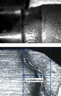 |
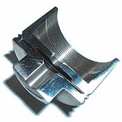
| Figure 1 Weld bead shape is critical in joining miniature devices, as shown in this completed GTAW bead (top) and laser-welded cross section. |
Several factors are important to keep in mind when the aim is to achieve a good-quality weld in a miniature device.
Weld Bead Shape. Weld bead shapes should transition to the base metal smoothly to prevent the development of stress concentration, which may lead to early fatigue failures. Undercutting, concavity, and other visual defects also can be detrimental (see Figure 1).
Weld penetration, called out by drawings or specifications, can be verified by macro- or micro-sectioning assemblies. Destructive testing often is used to ensure pressure integrity of the assembly at the required proof and burst pressures. Nondestructive testing methods also can be incorporated to ensure weld reliability for high-integrity applications.
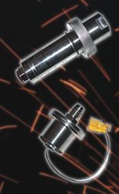
Metal Diaphragms. Metal diaphragms present another challenge to welding miniature electromechanical devices (see Figure 2). Frequently such devices employ diaphragms that can be as thin as 0.001 inch.
Thin components should be kept in intimate contact during fusion welding to control the thermal effects of welding, which can cause burn through or meltback. To prevent diaphragm failure during welding, a mechanical force should be applied to the diaphragm assembly, which is sandwiched between two thicker sections. Compressive-type tooling can be used with a spring-loaded tailstock or pneumatic piston.
Temperatures. Energy control is critical to avoid conducting excess heat into miniature devices. Thermal damage to sensitive electrical components, such as glass-to-metal seals or distortion of the thin diaphragms, can result from the slightest temperature increase.
 |
| Figure 2 The thinness of a diaphragm affords little resistance to bending or buckling, and diaphragms can be distorted by the heat of welding easily unless special precautions are taken. |
Excess thermal input also can create residual stresses. Inherent stresses can create long-term adverse effects, such as shortened fatigue life and calibration drifting. These concerns emphasize the importance of minimal heating and consistent control of the optimal fusion process.
Special Materials. Occasionally difficult-to-weld materials such as high-temperature aerospace alloys, nonferrous metals, and heat-treatable materials require special consideration in weld parameter development. The weld process and parameters should be considered carefully to preserve the special hardness, strength, or corrosion resistance for which the material was selected.
High-energy-density beam processes can apply precise thermal energy in close proximity to critical, heat-sensitive weld joints. Most often heat-sensitive components can be fusion-welded with a few watts of total energy input to the part.
Weld Joint Design. A weld joint can combine thin and thick materials, which can produce unbalanced heating during welding. For example, a thinner detail can melt back before a thicker member reaches its melting point. Solutions to this problem include using fixtures designed to cool the thin component and decreasing the heat imbalance.
Heating imbalances also can occur when materials with dissimilar thermal conductivity or melting points are welded, such as joining copper to stainless steel. In this case, high-energy-beam welding processes precisely focus and target the energy stream to favor the more conductive detail, thus delivering different energy levels to each of the components.
Joint design is critical for consistent weld quality, and because so many weld configurations are possible, this subject is too large for the scope of this article. In general, many joint configurations may be considered before a final configuration is chosen.
Because of these challenges, it's critical to understand the processes available for welding miniature devices, the differences between them, and what makes each suitable for certain applications.
 |
| Figure 3 This schematic of an electron beam welding machine shows how it uses highly concentrated thermal energy to join metal with deep penetration. |
The four most commonly used fusion welding processes for miniature-device manufacturing are:
Electron Beam Welding. In the late 1950s, German engineers introduced high-energy-density EBW. It can penetrate as little as a few thousandths of an inch to more than several centimeters in thickness. The stream of focused electrons can penetrate materials with low thermal conductivity to even greater extents (see Figure 3).
Performed in a high-vacuum environment, EBW offers virtually no chance of workpiece oxidation. EBW can be adapted for small production lots or prototypes. Computer-stored or documented parameters can be set up for repeated large or small production runs.
EBW lends itself to data acquisition for repeatability from part to part. Modern vacuum chambers with seals and pumping systems enable rapid chamber evacuation. Used with a microscope or video viewer, the electron beam can become a tool with resolutions of beam placement in the order of 0.001 in., making thin, critical welds commonplace.
Laser Beam Welding. By the early 1970s, laser beam energy began to emerge from university labs for use in joining miniature components for industrial applications (see Figure 4).
LBW can focus an energy beam into a spot diameter less than 0.010 in. The weld joint fit-up should be machined to close tolerances, with a joint gap of less than 0.003 in. desirable and no gap as the goal. Gaps exceeding 0.005 in. can result in insufficient fusion.
 |
| Figure 4 This diagram of a laser cavity and delivery optics illustrates how LBW focuses an energy beam into a spot diameter.; |
Occasionally filler metal can be used along the joint, but this adds to the cost of the process. Automatic wire feeding is available, but it often requires high energy levels not applicable for miniature devices.
LBW's low heat input, minimal defects, high metallurgical quality, and potential for high-volume automation can make the process cost-effective. Lasers can be automated, and laser focusing and beam delivery optics are readily incorporated in computer-programmed, multiaxis motion systems. High-volume production assemblies can be manipulated under programmed optic motion for welding.
With LBW, special environments aren't required for the laser to function. If inert gas shielding is required to protect the workpiece from oxidation, it can be controlled in the programmed weld parameters.
The laser produces a beam of concentrated electromagnetic radiation, free of restraining cables, electrical connections, and limiting arc length requirements. A collimated laser beam can be projected long distances to time-sharing workstations.
Generally, LBW is limited to a penetration depth of less than 0.100 in., and most commonly to 0.030 in. or less. Although high-power lasers are available that have greater penetration ability through keyhole techniques, they typically are more cost-effective for processes such as drilling, trepanning, and cutting.
Conversely, weld penetration capability of less than 0.100 in. encompasses nearly all miniature electromechanical device requirements accomplished with lasers with outputs less than 1 kilowatt.
Plasma Arc Welding. The plasma arc is achieved by first establishing the arc (and generating the plasma) inside the torch head. The plasma, at temperatures as high as 30,000 degrees F near the tungsten electrode, exits from the torch through a small-diameter constricting orifice. The orifice collimates the plasma and concentrates its energy into a beamlike, high-velocity stream.
The small-diameter, constrained plasma column provides directional control and produces narrower welds than GTAW. The plasma process produces deeper penetration than GTAW at the same energy levels.
Plasma arc equipment and power supplies incorporate electronic control circuitry and components necessary for repeatable weld processes. These features include control of pulse rates, pulse profiles, current sloping, and arc polarity. Though arc length is less critical with PAW than with GTAW, automatic arc length control also is integrated to accommodate variations in weld joint runout.
Gas Tungsten Arc Welding. Developed more than 50 years ago, GTAW can be integrated into fully automated systems, but it commonly is performed manually.
In the hands of a skilled welder, the process is flexible. With appropriate skill, the welder can adapt to joint configurations and compensate for fit-up tolerances and other variables through experience. A skilled welder can accommodate for joint gaps, mismatch, and other irregularities that would be unacceptable for precision automated machine welding.
Because GTAW is not machine-dependent, the need for precise and consistent joint preparation, though preferable, isn't necessary. Machine welding requires defined parameter development, as manipulation and correction during the course of the weld are limited. A skilled welder, on the other hand, assumes the role of machine, computer, axes of motion, scanner, and inspector.
The intrinsic value of manual welding, whether GTAW or PAW, is the welder's ability to produce high-quality welds with maximum flexibility and minimal capital investment. GTAW process integration requires minimal development and low capital equipment cost, although they can be offset by the labor-intensive nature of the process.
GTAW quality often depends on the welder's skill and consistency, so transfer of an operation from one welder to another or between shifts or facilities can be challenging. GTAW has many variables that limit it to specific automation techniques. In miniature-component welding, GTAW can be cost-effective for lower production volumes.
Each metal joining process has unique characteristics and ranges of capabilities. In selecting a process for a specific joining operation, users should scrutinize the requirements and conditions involved. Considerations include:
It's difficult to summarize or state without reservation which welding process should be used for maximum efficiency when joining miniature devices. Several variables exist across the previously described processes, but some generalities can help define a given process for miniature-component welding:
Michael Francoeur is president and founder of Joining Technologies LLC, Newgate International Business Center, 17 Connecticut South Drive, East Granby, CT 06026, 800-266-1966, fax 860-653-5777, mikef@joiningtech.com, www.joiningtech.com.


The Welder, formerly known as Practical Welding Today, is a showcase of the real people who make the products we use and work with every day. This magazine has served the welding community in North America well for more than 20 years.
start your free subscription
Easily access valuable industry resources now with full access to the digital edition of The Fabricator.

Easily access valuable industry resources now with full access to the digital edition of The Welder.

Easily access valuable industry resources now with full access to the digital edition of The Tube and Pipe Journal.

Easily access valuable industry resources now with full access to the digital edition of The Fabricator en Español.
In this episode of The Fabricator Podcast, Caleb Chamberlain, co-founder and CEO of OSH Cut, discusses his company’s...