


Bending Basics: Why do die angles change?
In air forming on a press brake, the die angle plays a subtle but critical role
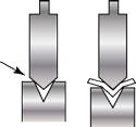
Figure 1: Mismatching the punch and die angle can create a dangerous situation. When the punch angle is larger than the die angle (as shown here), the die itself can split and, in some cases, explode.
From the beginning of the Industrial Revolution until air forming became the press brake bending method of choice in the 1970s and 1980s, fabricators all bottomed or coined sheet material. When bending plate or sheet to angles greater than 90 degrees complementary, they “formed” the material. It really was air forming, but at the time air forming as we know it was undefined as a process.
In coining, the dies were angularly cut to the set angle of the bend; a 90-degree punch and die set was used to produce a 90-degree bend. A 45-degree-complementary punch mated with a 135-degree-included die angle would “set” a 45-degree-complementary bend in the material. At the point of full contact between the die faces and material surfaces, punch face pressure was applied, and the material was thinned at the point of bend. Springback was nonexistent because the material was hit so hard that it realigned its molecular structure, leaving the material in a compromised condition.
Bottoming was a little different. The radius was still forced into the material, but there was an angular clearance between the die and punch faces. This reduced the forming tonnage dramatically, but still used the die angle as the set angle of the bend. Because most bending involves 90-degree bend angles, common dies were 90 degrees and the punches were either 90 or 88 degrees complementary.
Acute dies also existed for overbending at 45 and 30 degrees. But again, air forming had yet to be defined. Bending over an acute die was trial and error, using a test piece to develop the bend deduction.
Problems With Planed Tooling
So how did air forming evolve into a defined operation? It began in the late 1970s and early 1980s with the advent of precision-ground press brake tooling.
Before that time, all dies and punches, regardless of profile, were delivered in long sections. Only specials and custom tools could be ordered in specific lengths. This meant that punch and die sections had to be cut from the larger tool to create sets, and this was where problems began. If you did not get the punch and die set back into the exact order they were cut and facing the same direction, air forming was going to be a battle.
These planed-style press brake tools were rarely, if ever, marked in the way modern precision-ground tools are. You had no idea what the tool parameters were: tool number, load limits, radii, and angle. No two tools were alike, or even the same from end to end or side to side. True, it was only a few thousandths of an inch different from end to end, but even 0.003- to 0.005-in. variation from end to end on the tool could compound to an 0.008- to 0.010-in. difference if not mated properly. This had a profound effect on the finished product.
Enter Precision-ground Tools
Precision-ground tools are completely interchangeable, mateable, and have only 0.0004 to 0.0008 in. of error. That kind of precision, coupled with the CNC, allowed air forming to become a recognized, defined process. A workpiece could be consistently pushed between the now highly defined two top corners of the die and the nose of the punch, creating the angle of bend and the inside radius.
Air forming in practical terms means that the inside radius is a percentage of the die opening, based on material type, and the angle is set by the depth of penetration into the die. There is no full contact between the punch, die, and material. Therefore, the die angle has no direct effect on the air forming process. This also means you can quickly and easily produce the required parts regardless of the included angle of the die. A 30-degree die angle will produce the same radius as an 85-degree die angle; it is the width of the die opening that counts.
So why then do die angles change? There are two separate but overlapping answers; one relates to narrow die openings, and the other pertains to larger dies.
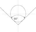
Figure 2: Unless customized, large-diameter round punches effectively have a punch angle of 90 degrees.
The Realm of the Small
Nonrelieved, precision-ground dies are (with exception) available in 90, 88, 85, 78, 73, 45, and 30 degrees. The reason die angles change in part is to compensate for springback. A narrower die angle allows for a greater amount of available penetration into the die space while forcing the material further around the punch nose during the forming process.
As the radius of the bend gets larger, the amount of springback increases. In a typical tool catalog you will find that, up to 0.05 in. of die opening, many widths are available, yet most dies are 90 degrees. From 0.5 to 1 in., the number of available die openings diminishes, and the angle changes to 88 degrees. From 1 to 2 in., the die opening selection diminishes further, and the die angle changes to 85 degrees. (This example is for a general discussion; specific tooling manufacturer catalogs may differ.)
If you use a die opening less than 0.5 in., your material is thin and the radius small with little or no springback. If you use a die opening from 0.5 to 1 in., you’re usually working with a larger-radius bend. A large radius will have more springback, so the included die angles get smaller. From 1 to 2 in., the included angle selection diminishes again, and the degree of those included die angles decreases even more—again, because larger dies usually form bigger radii with even more springback.
Use caution when selecting the punch angle, which must be equal to or less than the included angle of the die (see Figure 1). If you try to mate an 85-degree die with a 90-degree punch, the tools will directly interact and the die will split. If this happens with tools hardened to somewhere near a Rockwell 75, they will explode and throw shrapnel.
One last consideration covers minimum flange width. The smaller the included angle of the die, the greater the required minimum flange width. For this reason you may need to review the included die angle based on the required minimum flanges.
For instance, for a 90-degree die, the minimum flange from the edge of the workpiece to the bend line equals 70 percent of the die opening. So by multiplying a 90-degree die’s opening by 0.7, you know the minimum flange dimension. When you have a 30-degree die angle, the multiplier is 1.5 times greater than that of a 90-degree die, which increases the required minimum flange width.
In the realm of the small, you need to review the die opening and minimum flange width when you select a die angle. You need to find the die with the narrowest included angle capable of producing the minimum flange-dimension values and the proper die opening to float the required inside radius, based on the 20 percent rule (see sidebar).
In the Realm of Giants
In the realm of the small, die openings and angles are plentiful, but in the realm of the large, this isn’t the case. Custom-designed tools aside, large-radius punches are commonly made from barstock or thick-walled tubing. These round punches effectively have a punch angle of 90 degrees (see Figure 2).
In the realm of the small, if you have 2 degrees of springback, you need a punch with an angle that’s 2 degrees less than the die angle to provide the needed clearance. But again, as the radius increases, so will springback. In sheet metal, springback can be as high as 60 degrees—so how do you compensate for that?
Enter the relieved die (see Figure 3). Here the die space has been relieved, and there is no contact between the punch and the die face. This allows the punch to pass deeply into the die space and, to compensate for springback, take advantage of a 78- or 73-degree-included die angle.
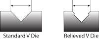
Figure 3: A relieved die face allows the punch to descend farther into the die space. This can be critical when compensating for springback in large-radius applications.
In this case, though, another situation arises: multi- breakage (see Figure 4). Because you are pushing a 90-degree punch into a 73-degree relieved die, the inside radius of the bend will be much smaller than the radius of the punch. And because you’re bending acute, 30 to 60 degrees past 90 degrees (again, for springback), the radius in the part will become tighter than the punch radius during forming. Note that this may occur even in small-radius bends, but in large-radius bends the effect becomes more pronounced.
Sure, you could calculate the required punch radius necessary to float the desired bend radius precisely, but that is very difficult to do. The best way to mitigate this effect is to add a shaped, low-durometer urethane pad in the bottom of the die. If a urethane pad is unavailable, a section of high-pressure water hose will serve the same purpose. As the material pushes into the pad, the pad pushes back against the sheet, forcing it to take on the radius of the tool while still allowing for deep penetration into the die space and the ability to incorporate the narrow die angle.
(Note that there are many other styles of dies, such as Rolla-V and special urethane tools, designed specifically for large-radius bends in sheet metal. These work on different principles than the dies discussed here.)
Forethought for Every Realm
Selecting the right die angle and width requires a little forethought based on the product and material, especially now that toolmakers are adding more width and angle options—89 or 87 degrees, for example. Some are starting to produce punch and die angles in 0.5-degree increments.
When selecting your tool, be sure that you match the punch and die angle correctly. In the realm of the small, the die angle should be equal to or greater than that of the punch. In the realm of the large, you need to account for multibreakage, and the die angle should be relieved to allow for springback compensation.
During air forming, the bend angle is not based directly on the die angle, but that doesn’t make the die angle any less critical. Selecting the wrong die angle at best can cause major accuracy and setup problems. At worst—when the punch angle is actually wider than the die angle—it can create a dangerous, even life-threatening situation.
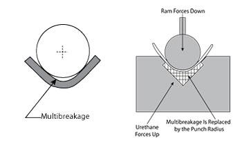
Figure 4: In a large-radius bend, multibreakage occurs, in which the radius tightens and does not conform to the punch radius during forming. You can mitigate this effect by inserting a urethane pad at the bottom of the die.
About the Author

About the Publication
subscribe now

The Fabricator is North America's leading magazine for the metal forming and fabricating industry. The magazine delivers the news, technical articles, and case histories that enable fabricators to do their jobs more efficiently. The Fabricator has served the industry since 1970.
start your free subscription- Stay connected from anywhere

Easily access valuable industry resources now with full access to the digital edition of The Fabricator.

Easily access valuable industry resources now with full access to the digital edition of The Welder.

Easily access valuable industry resources now with full access to the digital edition of The Tube and Pipe Journal.

Easily access valuable industry resources now with full access to the digital edition of The Fabricator en Español.
- Podcasting

In this episode of The Fabricator Podcast, Caleb Chamberlain, co-founder and CEO of OSH Cut, discusses his company’s...
- Trending Articles
1
AI, machine learning, and the future of metal fabrication

2
Employee ownership: The best way to ensure engagement

3
Steel industry reacts to Nucor’s new weekly published HRC price

4
Dynamic Metal blossoms with each passing year

5
Metal fabrication management: A guide for new supervisors
