


Territory Sales Manager, South East
It is forecast that worldwide supply of industrial robots in 2016 will have grown by 15 percent since 2015 to more than 256,000 units. These record sales were experienced primarily by large OEMs and tier suppliers in the automotive segment, but small to medium-sized manufacturers just beginning to explore the use of robotics are also at the core of this record market growth. North America remains third in number of robots installed and in use today behind Japan and China.
So, why do factories automate their processes?
Still, before shop managers install a robotic welding and joining system, they should understand all of its components and their functions.
The robot is only a part of a robot-based automation system, whether the system is for welding or other applications.
Regardless of the application, several components and functions are common to all systems. Controls, communication devices, operator interfaces, sensors, peripheral equipment, parts handling equipment, fixtures, safety features, and cable management devices are common components in all systems. Most projects require some personnel involvement as well.
Controls, communication instruments, and operator interface components are interrelated in automation systems. System controls include both the robot controller and other system controllers like PLCs and PCs. Generally, robot controllers are tasked with controlling robot tooling and providing robot motion, while system controllers provide logic through inputs and outputs for events like parts movement, communication to the production environment, system data acquisition, and human interface. The system controllers’ function is to verify that system conditions are met and to communicate with the robot controller to execute its program.
The operator interface is how plant personnel see system status and is the means to input any externally initiated process modifications. Considerations in operator interface designs include the level of human (operator) involvement with the system, any desired part quality input decisions before the robot processes them, and desired notification when the system requires operator intervention.
Pneumatic Components. Valves, fittings, air filters, pressure sensors, regulators, lubricators, and lube filters as well as actuators for tooling and parts fixtures are part of the automation system. Pneumatics are used for gripper actuation and vacuum generation, either on the robot tool, as in material handling, or to actuate part-holding clamps and vacuum hold-downs for welding.
Sensors. These are used to verify action and locate parts. The use of electromechanical devices such as whisker switches, proximity-type, hall effect-type switches on air cylinders, and those that detect when a light beam is broken are examples of the types of sensors used to detect the presence of a part or verify an action. They are required to provide positive system control. And if system requirements demand it, a camera or a vision system can detect part location, orientation, and even perform part quality checks.
A pick-and-place application is an example of system sensor use. A robot cannot move to pick up a part until a presence sensor indicates that a part is in the pick position and another sensor confirms that the gripper is open and ready to pick up a part. When the robot moves to the pick position, a gripper sensor confirms that the gripper has closed on the part, and a part presence sensor on the tool indicates that a part is in the gripper. A closed gripper, a part in the tool, and no part in the pick position indicate that a part is traveling in the tool.
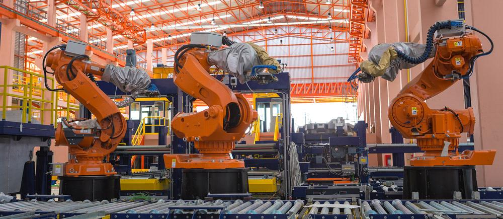
Side bar photo
At the “place” location (the destination), a sensor verifies that the place position is open to receive a part. Again, the part must be in position, the gripper open, and no part detected on the tool after the robot moves away. This is a positive indication that a part has been moved as expected. This example illustrates how sensors can be used to provide positive feedback that a part was picked and placed as expected.
In welding it is common to employ sensors to detect part clamp positions, part presence, and in some instances detect which weld fixture is in use to verify that the fixture matches the part that matches the welding program selected in the robot. In addition to commonly available sensors, a process in welding known as touch sensing can be used to verify part locations and sizes and can check physical attributes of a part as verification prior to welding.
Electrical Components. Automation systems also may require electrical components such as connection boxes, transformers, motor starters, external axis motors, and drives along with the required safety system controls.
Safety system components include personnel barriers, access doors, door switches, awareness beacons, control system interlocks, and signage. Safety systems must be designed to conform with the American National Standard for Industrial Robots and Robot Systems (ANSI/RIA R15.06-2012).
When human interaction with the robot is allowed under certain controlled, safety-rated conditions, it is called a collaborative system. These system requirements are detailed in the recently published ISO Technical Specification ISO/TS 15066:2016, Collaborative Robots.
In addition to the standard automation system safety components, fume extraction and eye protection against weld flash are required equipment for welding.
Items such as a robot riser or mounts, turntables and conveyors for part presentation, part fixtures, tooling, nests, and other processing equipment or hardware that may be required to perform the work are all part of the robot-based automation system.
Cable management in an automated system often is overlooked until it becomes a problem. Problems include cable damage caused by repeat flexing; shorts caused by cable wear; disconnected cables caused by motion; and cable damage by forklifts. Cables must be routed in and out of the system; between the robot and the robot controller; between the robot controller and the system controller; between pieces of peripheral equipment; and between connection boxes and safety components.
Cables fixed to the robot arm, known as dressing, must be high flex-rated and routed with full robot motion considered. Power drops, cables between system components, and connection boxes are stationary, so they do not require high-flex cables. It is optimal to use the internal wiring provided by the robot manufacturer, but quite often cables must be dressed outside the robot arm.
Dressing also includes other items mounted on the outside of the robot arm such as pneumatic lines, cooling water lines, and material dispensing hoses. Robot motion must be considered when dressing any of these items.
Dressing for welding includes the torch cable, hose package, weld wire conduit, and any sensors that run outside the robot arm.
Although robot-based automation systems reduce direct labor costs, they require personnel to handle certain tasks. These include project management, system simulation and layout, system development, design, programming, proof-of-concept testing, and system mockup. In addition, the systems require people to perform runoff before shipping, system shipping, installation, site preparation for new equipment, and commissioning. Budgets should allocate funding for both operators and management training.
Welding systems will require tooling design to properly hold parts for automated welding.
The last component to consider in a robot-based welding system is the actual robot. The robot is selected using three criteria: reach, or area that it can access; payload, or weight-carrying capacity; and speed. In welding applications, the robot’s payload must be rated to handle the torch, breakaway, insulating disc, wire feeder, and torch cable load on the arm. The robot’s reach must be sufficient for it to articulate, access, and move to reach all the required weld points on the parts. The robot controller requires welding software that provides the means to communicate to the welding power supply and to interpret the need for motion changes to optimize the welding process.
The production rate required has to include the robot’s speed in performing all the welds on the part plus its air movements.
Welding is a mature application for industrial robotics, so most robot manufacturers offer welding-specific robots complete with the features necessary to provide the fabricator with a proven product for welding success.
Robot tooling in any robot-based automation system is the most important component in the system. In a welding system, the welding power supply, wire feeder, torch, cleaning station, and all the ancillary components of the welding system comprise the tooling, and they are the key to success in these automation systems (see Welding System-specific Components sidebar).
Bob Rochelle is territory sales manager, south east, for Güdel Inc., 734-214-0000, Ext. 9048, bob.rochelle@us.gudel.com, www.gudel.com/us.
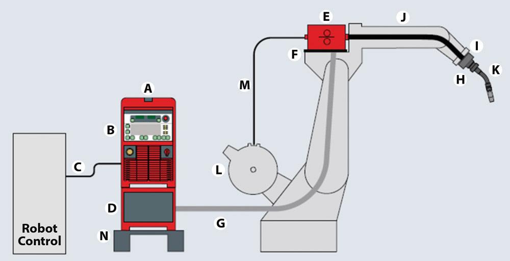
(A) The welding power source is the heart of the welding system. It provides the necessary power to generate the heat to liquefy the metal at the end of the torch so that the metal parts are joined (welded) together. The power source selection is a function of the type of welding that is required in the system. Installation of the power source typically requires three-phase power.
(B) The interface allows the robot controller and the welding power supply to communicate. This constant communication monitors weld performance and modifies robot weaving, power source settings, robot speed, and many other parameters that affect weld quality. Many different options for interface communication are available, including discrete, bus protocol, and Ethernet-based.
(C) The interface communication cable is the cable that connects the welding power source to the robot controller.
(D) For welding that requires a water-cooled torch, a water cooler is required. Water coolers require coolant and power for operation. Coolant lines need to be connected and dressed externally to the robot arm.
(E) The wire feeder supplies the weld wire to the torch for the welding process, and it needs to be matched to the voltage and current capability of the welding power supply. In wire feed welding the amount of wire protruding from the torch tip is very important, and the wire feed rate must be controlled to maintain this protrusion to generate a quality weld. The wire feeder’s communication cable must be plugged in; a shielding gas hose must be connected; and drive rolls must be installed and maintained for proper operation.
(F) The wire feeder bracket mounts the wire feeder to the robot and provides insulation between it and the robot.
(G) The hose package contains the wire feeder communication cable, positive or negative lead for the self-shielded wire, shielding gas hose, and coolant lines if needed.
(H) A torch breakaway or collision box provides a mechanical way for the torch to disconnect in the event of a collision. Many users also employ the robot collision detection software offered by the robot manufacturers to protect the torch from damage. This can be used with or without the mechanical breakaway.
(I) An insulation disc is required between the torch or any mechanical breakaway and the tool mounting plate on the robot.
(J) A torch cable, or whip, connects the torch with the wire feeder and provides the connection for the torch tip use.
(K) The torch neck, or gooseneck, is the actual welding torch.
(L) The weld wire holder supplies the bulk wire to the wire feeder for consumption in the welding process. Typical weld wire holders are either a spool type or a barrel.
(M) The weld wire conduit, installed between the wire feeder and the welding wire holder, provides the conduit for the wire to travel to the wire feeder.
(N) The power source stand is used to mount the welding power supply.
Not shown in the diagram is a torch-cleaning station. This is required because a robot-based welding system typically must work at or near maximum speed, so it has little time to recover between welding operations. Because of this and the need to maintain the integrity of welds, the torch must be kept clean. This cleaning occurs when parts are switched. Cleaning and trimming the wire properly to the correct protrusion ensure that each weld starts with the optimal conditions to produce a quality weld and part.


The Fabricator is North America's leading magazine for the metal forming and fabricating industry. The magazine delivers the news, technical articles, and case histories that enable fabricators to do their jobs more efficiently. The Fabricator has served the industry since 1970.
start your free subscription
Easily access valuable industry resources now with full access to the digital edition of The Fabricator.

Easily access valuable industry resources now with full access to the digital edition of The Welder.

Easily access valuable industry resources now with full access to the digital edition of The Tube and Pipe Journal.

Easily access valuable industry resources now with full access to the digital edition of The Fabricator en Español.
In this episode of The Fabricator Podcast, Caleb Chamberlain, co-founder and CEO of OSH Cut, discusses his company’s...


