


Intelligent Robotic Welding
 |
Robotic arc welding has become a mainstay of the manufacturing community, meaning robotic welding vendors no longer have to prove to a customer that a robot can weld. Now customers are asking new questions such as "How can I weld low-volume, multiple part styles in the same workcell?" and "How can I eliminate the downtime to program a new part?" These types of questions point toward the next era in robotic arc welding known as intelligent robotic welding.
Illustrated in Figure 1is the Intelligent Circle for robotic arc welding. The circle implies a continuous flow from element to element and an interdependency to complete the ring. If one element is missing or lacking in performance, the whole unit can act more like a flat tire than a dynamic process.
Going With the Flow
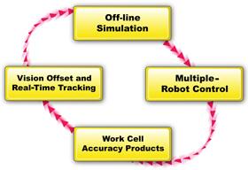 |
| Figure 1 If one element of the Intelligent Circle is missing, the entire unit will fail. |
An intelligent robotic welding workcell requires a lot of preplanning for the cell design and process flow. This key ingredient depends on an accurate model of the workcell with offline computer simulation, such as the one shown in Figure 2. In robotic simulation it is critical that the model created accurately reflects the real-world nature of the physical devices as well as the operation control. It's not enough just to have an accurate mechanical model; the simulation must also provide accurate program operation and cycle time calculation. The simulation must provide the tools to import 3-D CAD models of parts and easily create robot programs utilizing CAD-to-path methods. The user interface must be designed for welders who understand welding processes such as torch angles and travel direction so that they can quickly visualize the desired welding conditions in the model. Programs created in the simulation should be complete and ready for downloading to the robot without the need to be translated or compiled to help avoid time-consuming errors or extra programming.
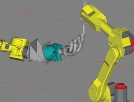 |
| Figure 2 This computer simulation shows one robot holding a part while another robot performs the weld. |
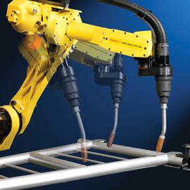
To achieve the maximum utilization from a robotic welding cell, it is advantageous to use multiple robots within the same work zone, shown in Figure 3. These robots then can be controlled from a single controller in a coordinated fashion to maximize reach and reduce tooling costs. For instance, a flexible workcell can be created by using one or two robots for material handling while other robots perform welding. With a change of end-of-arm-tooling (EOAT) on the material handling robots, a variety of parts can be welded within a single workcell.
This flexible manufacturing method with limited or simplified fixtures and tooling (often referred to as "jigless") has a lot of merit for some manufacturers, especially those with a variety of low- to medium-volume parts. In addition, safety in a multiple- robot cell is a prime consideration. All robots within the cell must comply with the requirements for single-point safety control in accordance with ANSI/RIA R15.06-1999 requirements.
Calibration Time
Now that we have an accurate computer model and the physical workcell, we need to calibrate the virtual and real worlds. The simulation world is basically perfect, with all of the elements precisely configured and located. But the real-world workcell is full of build variation. Several elements within the workcell must be calibrated, such as the robot to its EOAT, robot to robot, and robot to parts or fixtures. These processes rely on automated utilities within the robot to perform the calibration automatically without variances caused by human setup methods. No two operators, or even the same operator, can perform a calibration routine in a repeatable manner. The automated method also provides a means of recovering from an error condition—such as a broken EOAT— to maintain the workcell accurately. This ability to establish calibration and recover from real-life occurrences is critical to the success of an intelligent robotic welding workcell.
Another key consideration in an intelligent robotic welding workcell is that parts have variations. The virtual world deals only with perfect parts—exactly what the CAD model says they should be. The real parts, conversely, vary from the design and from part to part. This necessitates the need for the last elements of the Intelligent Circle: vision offset and real-time tracking.
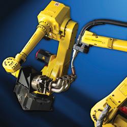 | 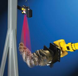 |
| Figure 3 The robots are then calibrated to perform specified functions from the simulations. | Figure 4 Using a vision system in the workcell helps to detect part variation. |
Vision systems (see Figure 4) in either a 2-D or 3-D configuration can compensate for variations from part to part, giving the calibrated workcell the final offset needed to place the weld in the joint as required. This system must seamlessly integrate into the robotic cell, providing the required data without delay to the operation. User interface and ease of program creation must be scrutinized when choosing such a system. Some parts also can (or alternately) be programmed to use touch sensing to find part offsets or arc seam tracking to follow the actual seam in real time while welding. All of these tools essentially give the workcell "eyes" to make the required adjustments from the virtual world.
All of these individual elements are essential to the success of a welding workcell that is both flexible and intelligent.
Michael Erickson is senior engineer, Materials Joining Segment at FANUC Robotics America, 3900 W. Hamlin Road, Rochester Hills, MI 48309-3253, 248-377-7000, www.fanucrobotics.com.
About the Author
About the Publication

subscribe now

The Tube and Pipe Journal became the first magazine dedicated to serving the metal tube and pipe industry in 1990. Today, it remains the only North American publication devoted to this industry, and it has become the most trusted source of information for tube and pipe professionals.
start your free subscription- Stay connected from anywhere

Easily access valuable industry resources now with full access to the digital edition of The Fabricator.

Easily access valuable industry resources now with full access to the digital edition of The Welder.

Easily access valuable industry resources now with full access to the digital edition of The Tube and Pipe Journal.

Easily access valuable industry resources now with full access to the digital edition of The Fabricator en Español.
- Podcasting

In this episode of The Fabricator Podcast, Caleb Chamberlain, co-founder and CEO of OSH Cut, discusses his company’s...
- Trending Articles
1
Team Industries names director of advanced technology and manufacturing

2
Orbital tube welding webinar to be held April 23

3
Chain hoist offers 60-ft. remote control range

4
Push-feeding saw station cuts nonferrous metals

5
Corrosion-inhibiting coating can be peeled off after use
