


Arc Welding Manager
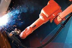
Figure 1: Robotic welding innovations have resulted in systems that are flexible enough to tackle heavy fabrication work.
Making your first steps into automating the welding of heavy fabrications can be a daunting task if you don’t have a deep background in this subject area. You know you have the need, but you are not sure how to tackle the problem, or even whom to go to for support. Often the mission is further complicated if your operation produces many part types and variants, mostly in low batches.
The good news is that a fabricator can follow a core set of steps to ensure a successful venture into the world of robotic welding of heavy fabrications. Whether you undertake this activity with internal resources or look to an experienced external partner, the steps are basically the same.
Of course, any process starts with the people. Selecting an effective team will increase the chance of a successful outcome significantly. The selection of your team is scalable to the size of your organization. The necessary traits may lie within an individual or multiple people. A sense of project ownership, enthusiasm, and drive should be shared by all. Additionally, they should welcome new ideas, especially the person who will be responsible for the day-to-day operation of the new automation system. Another character trait to look for is foresight—the ability to understand on both the macro and micro levels the implications and ramifications of what new methodologies may bring to a process.
With the team in place, you can set about the task of qualifying and quantifying what should be considered for automation. At this point you should take a holistic approach. Review the complete fabrication process with regard to your products. You are looking to collect a list of all the possible products worthy of automation. As the list takes shape, you can start to group the components into families or groups—by joint type, material type, product family, or perhaps process constraints. You are looking for patterns, not necessarily parts of a common type, but perhaps the repetition of the same joint type within a group of components.
It is key to keep an open mind. The way you do it today may not be the way you do it in the future with automation. New processes, sequences of operations, or complete fabrication methodology should be considered. Often gas tungsten arc welding is thought of as the only way a product can be made. Robotic automation can bring other joining processes into play, like advanced gas metal arc welding (GMAW) with low heat input.
Generally, robots like repetition, something that is typically not applicable to welding large, heavy fabrications. Compensatory processes and devices are therefore required. In this phase of consideration, the detailed eye comes into play. Each of the selected components on the wish list of products to be welded through automation should be reviewed down to the joint level. Here considerations of joint type, material, size and length of weld, number of passes, overall stackup of manufacturing, and process tolerances must be taken into account.
What will start to emerge is a table of components and joints portraying the level of ease or complexity required for automation. At this point you should consider the tools available to meet the typical demands of welding heavy fabrications (see Figure 1). These are reviewed next in the order of cost and complexity, progressing from low to high.
Tactile Sensing. The most prolific impediment to setting up robotic welding of heavy fabrications is that the joint cannot be placed cost-effectively in the same position for each product. This is addressed traditionally by the use of a tactile sensing system (see Figure 2).
In this type of system, voltage is applied to either the wire, gas shroud, or even a retracting probe, which becomes the tactile sensing means for the robot. The robot then carries out a search pattern in as many planes as is required to deduce the relationship between the original programmed point and the current position of the weld.
Tactile sensing systems are widely used and a trusted technology for cost-effectively locating joints on heavy weldments. The downside is that mill scale and other material defects sometimes can affect the quality of the search.
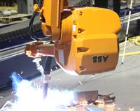
Figure 2: Robotic welding torches that rely on tactile sensing typically need only one to three seconds to locate a joint.
With the recent introduction of a laser sensor, the tactile approach to searching has been much improved. The sensing laser has an accuracy measured in microns and reacts at the speed of light. As a light beam, it can point into restricted areas where a torch/wire combination could be challenged. In the hands of a skilled programmer, a sequence of searches can provide fast, accurate positional data for the robot to act upon. Thanks to the technology advances, material condition and shiny surfaces do not present a problem to this technology.
Through-the-Arc Tracking. After it has been determined how the robot will find the joint, the question is, Can the robot get to the end reliably without further input? If the robot’s path is impeded, further searches may be required. If the weld joint cross section or gap varies along its length, then further sensing levels are required.
An adaptive sensing system offers two levels of through-the-arc tracking. Using impedance the system can measure the voltage and current as the weaving of the joint takes place; an optimal path is achieved as a result. If the joint also changes in volume along the path, the adaptive sensing systems can vary the process to compensate for the fill requirement. If multipass welds are required, the same sensing technology will record and displace the subsequent strings by the required offsets to achieve correct fusion, penetration, and fill characteristics.
Tactile sensing or a laser sensor also can be used to create these types of adaptive fill techniques.
Laser/Vision Guidance. A laser- or vision-based guidance system typically is required for more demanding joint types, where through-the-arc tracking may not provide enough data to guide the robot.
Over the last few years, these guidance systems have continued to improve in value and functionality. Technology integrators, which incorporate their own laser/vision guidance products on OEMs’ welding equipment, provide systems that deliver accurate and reliable data for welding the most demanding joints. These systems are able to plot the position and capture all the critical variables to ensure the robot is able to produce a suitable weld for that specific joint.
Many welding processes can work in conjunction with the sensors to resolve any welding challenge.
Conventional single-wire GMAW is most common, but the introduction of a second wire may meet your special needs. Combinations of plasma, laser, powder, wires, and gases also can come into play, with each providing a unique characteristic to achieve a successful outcome.
It is becoming more common to have robotic tool changers that enable the robot to carry out multiple processes. For example, a robot could be equipped with single-wire GMAW capabilities to weld certain strategic parts of the assembly with poor accessibility and, after a tool change, a twin-wire torch to provide high deposition for other welds (see Figure 3).
Welding power supplies from different manufacturers all have differing capabilities. They, too, continue to overcome the barriers to obtain the perfect weld in arduous circumstances. One such development is the ability to reverse the DC polarity, enabling very low heat input and allowing robots to carry out effective root runs.
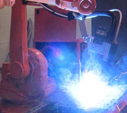
Figure 3: A GMAW process with twin wire is a great way to fill large welding gaps often associated with heavy fabrications.
Tacking the components is always a hot topic and another thing to keep in mind. How many tacks are needed? Where are they needed? What size should they be? Is a fixture needed for the heavy weldment? Is hard tooling needed? Getting to the right answer can take a little time. It is difficult for one answer to fit all situations, but if you break down your approach, a viable solution usually can be found.
For example, consider an assembly of components that need to be placed in a controlled relationship to each other, so once the weld process is complete, the item is ready for the next step of production. The ideal scenario, of course, would be for the fabrication to require no other secondary processes, such as straightening or cleaning, before its next manufacturing sequence or need rework or repair to meet the appropriate production specs.
If the components can be designed to self-jig, then simple placement into the robot work envelope and some strategic tacking will be all that is required. The goal is to have the least number of tacks so that the product remains stable during the welding process, avoiding the opening or closing of gaps and achieving the required manufacturing tolerances. Tacks should be uniform and consistently placed to minimize the impact on process. Development of the welding procedure often moves or varies the number of tacks in an operation to achieve this goal.
The thermal impact of welding is another consideration. As a part of product design, a certain alloy is selected to deliver very specific characteristics that enable it to function as required. The joining process should not dilute or degrade the product and, in the right circumstances, might even provide an enhancement.
Simple sequential robotic welding can control the heat input delivered to large fabrications. Automation lends itself very well to introducing the optimal amount of weld and heat in the right place at the right time, day in and day out.
Further enhancements can come from the use of thermocouples logically linked into the robot controller. These sensors can protect the fabrication, so that the robot welds only when operating conditions fall within predetermined parameters. For example, when it comes to welding a particular steel alloy, a welding robot might be limited to welding within a defined window of temperature. A few strategically placed thermocouples in series, monitored by the robot controller, will ensure welding takes place only in the optimum conditions.
It should be noted that the robot’s ability to process large amounts of data is very useful. This is put to good use when the weld attributes are being monitored. In some instances, the fabricator might be interested in simply gathering historical data for traceability.
It’s most important, however, that the robot’s information-processing capability interacts with the welding process itself. Once an optimum process is established, the welding robot operator can input the usable upper and lower limits of the arc characteristics. The logic of the robot program then ensures the welding process doesn’t deviate from that defined range. This feature eliminates the risk of producing scrap or unwanted rework, while simultaneously ensuring the application of uniform heat input.
The good thing about robots is that they always know where they are in space. This is particularly helpful in ensuring the right amount of weld is deposited within a joint that is inconsistent.
Some robots are programmed using the tool-center point (TCP), which refers to the robot’s position as well as the focal point of the tool. The ability to do this type of programming is particularly useful because, by knowing where the traveling TCP is in space, the operator can make important decisions during the welding process. If a joint, for example, requires 10 passes to provide the correct fill, each string or layer of strings can be defined and called up by virtue of position.
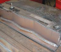
Figure 4: This reinforcement plate for an off-road vehicle chassis once took several minutes for a welder to fabricate manually. Now a robotic welding cell can turn out these heavy weldments in a fraction of the time.
The A string would be used until a certain height was achieved, and then the B string would be selected. The welding robot could continue with the B string or move on to another type of string until the cap was completed. This approach provides a uniform fill with feedback, avoiding over- or underfilled weld joints.
Welding heavy fabrications with robots (see Figure 4) doesn’t have to be a process filled with mystery—especially if you have a robotic eye looking out for you.

The Fabricator is North America's leading magazine for the metal forming and fabricating industry. The magazine delivers the news, technical articles, and case histories that enable fabricators to do their jobs more efficiently. The Fabricator has served the industry since 1970.
start your free subscription
Easily access valuable industry resources now with full access to the digital edition of The Fabricator.

Easily access valuable industry resources now with full access to the digital edition of The Welder.

Easily access valuable industry resources now with full access to the digital edition of The Tube and Pipe Journal.

Easily access valuable industry resources now with full access to the digital edition of The Fabricator en Español.
In this episode of The Fabricator Podcast, Caleb Chamberlain, co-founder and CEO of OSH Cut, discusses his company’s...


