


Sales Manager
Clamping is one of the key operations in the rotary draw tube bending process. The other operations are limited in their capacity to compensate for insufficient clamping. Poor clamping—that is, clamping that allows the tube to slip during bending—results in the loss of process control. Getting it right is fundamental to a sound bending process.
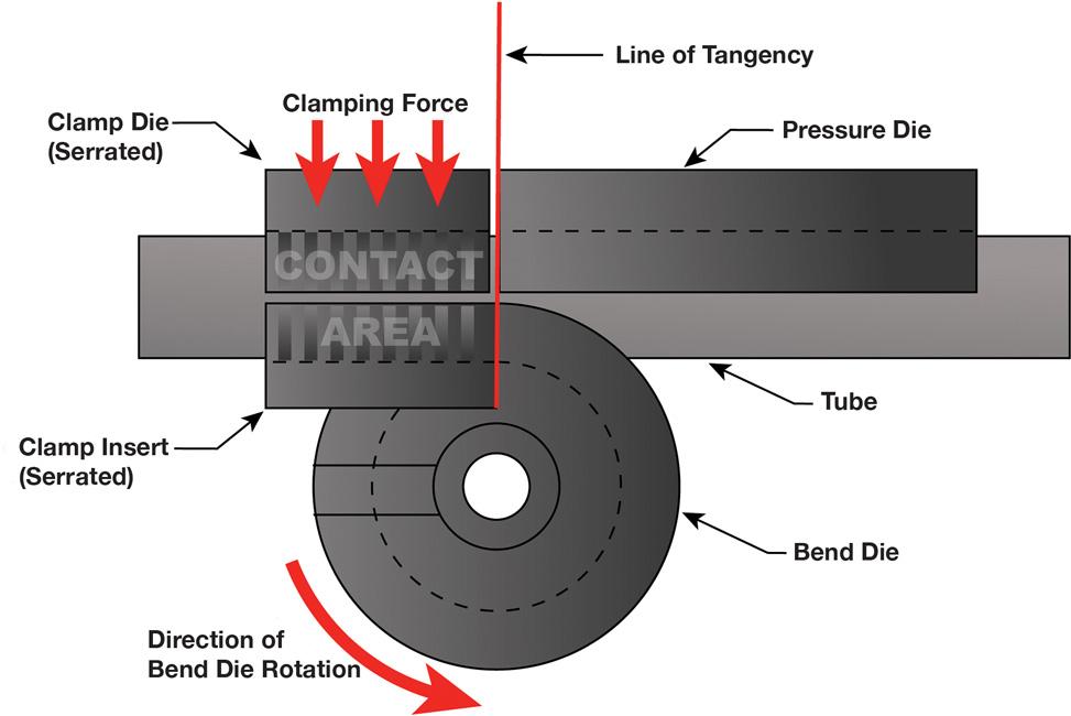
Clamping fixes the position of the lead tangent of a tube bend so that the trailing portion of the tube is under constant tension as it is drawn through the line of tangency and formed into the arc of the bend. Secure clamping of the lead tangent to the bend die does this. If the position of the lead tangent is not fixed relative to the remainder of the tube, the bend will be formed under variations in tension. These variations, depending on the counteracting effects of the pressure die, can manifest themselves as wrinkles and even ruptures in the bend.
Increasing clamping force pressure—the force that holds the tube in place—usually eliminates such problems. This is because the tension of the draw is produced by the friction between the clamps and the tube, and pressure is one of the three factors of friction. The other two are contact area and material coefficient, the latter of which may be understood as grip. These three factors relate to friction by the following formula:
Friction = Pressure × Contact Area × Material Coefficient
The two mechanisms involved in the clamping process are the bending machine and the clamp dies. The bend machine provides the pressure, while the clamp dies provide the other two factors. After the clamp die material has been specified and the clamps have been manufactured, the material coefficient and contact area are fixed. The only variable is the clamp pressure, which is why many fabricators rely on this sole factor to overcome poor clamping.
There is only so much that can be corrected by pressure. For that reason, it is important to specify the clamp dies so that the contact area and the material coefficient are sufficient for the bend to be produced. The relevant clamp die specifications are cavity diameter, cavity length, and cavity surface. Diameter and length determine the contact area. The surface determines the material coefficient. As is evident from the formula for friction, the larger the contact area, the lower the material coefficient needed, and vice versa.
Let’s review these specifications one by one. Cavity diameter is critical. If it is too large, then the tube will slip loose from the clamp dies. If it is too small, there will be no slippage but the tube will become marked with an impression of the clamp dies. (Note: When marking is not an issue and there are constraints on other clamping methods, an undersized cavity diameter may be desirable because it “bites” into the tube. This is discussed later.) The optimal specification of the cavity diameter eliminates slippage without marking the tube.
Because cavity diameter varies within a very tight range, in the thousandths of an inch (or hundredths of a millimeter), cavity length is the only variable to be considered to change the size of the contact area. Generally the smaller the D of bend, which is the ratio of the centerline radius of the bend to the tube’s OD, the larger the contact area needed, assuming no change in the material coefficient. Therefore, the longer the cavity length is, the larger the contact area is.
This relationship has been reduced by experience over the past half-century to a rule of thumb. A 2×D bend requires a smooth-surfaced cavity length that is two times the tube diameter. The cavity length increases to three times the tube diameter at the limit of a 1×D bend. Conversely, the cavity length decreases to a minimum of one times the tube diameter for a 5×D bend. Secondary variables such as a heavier wall thickness, a larger degree of bend, or a more rigid material may require increasing the cavity length more than the rule of thumb recommends.
The rule of thumb is based on a preference for a smooth cavity surface because it is the surface least likely to mark the tube. However, the cavity length required for a smooth cavity surface often is not possible, practical, or even preferred. Three examples of this situation are the lead tangent is shorter than the preferred smooth cavity length; stacked-die tooling allows only minimal variation in cavity lengths; or the application is for such large-diameter tube that the cost of the clamp die is not practical.
The answer to decreasing the cavity length while maintaining sufficient friction is to increase the material coefficient of the cavity surface, or in common parlance, the grip of the clamp. Serrations and impregnated grit increase the grip, and they are available in a range of grades from fine to coarse. The finer they are, the less they mark; the coarser they are, the more they grip. Therefore, specifying the cavity surface is a trade-off between marking and grip.
In some cases, the lead tangent is so short or one of the secondary variables is so extreme that serrations or grit alone is not sufficient to provide enough grip for the application. This is when the cavity diameter is undersized so that it bites into the tube. Strictly speaking, bite does not increase the material coefficient of the cavity surface. Instead, it increases its contact area with the tube. This is because the teeth of the bite push into the tubing material and literally enlarge the contact area. Of course, the drawback to a cavity surface with bite is the significant marking of the tube.
Common sense makes clear what clamp dies must do for a good tube bend. The principles underlying this common sense are not difficult to understand. The key to secure clamping is friction, and friction is determined by three factors: pressure, contact area, and material coefficient. The bending machine provides the pressure. The clamp dies provide the contact area and material coefficient. In turn, the clamp die specifications of cavity diameter and cavity length determine the contact area, and cavity surface determines the material coefficient, or grip.
Translating the tube bend specifications into effective clamp die specifications means using enough grip. Too little grip leads to slippage, and too much grip causes unacceptable marking of the tube. The trade-off in clamping comes down to grip and marking. Understanding what your priorities are as the fabricator will assist the designer of your clamp dies to balance the tooling specifications to meet your requirements.


The Tube and Pipe Journal became the first magazine dedicated to serving the metal tube and pipe industry in 1990. Today, it remains the only North American publication devoted to this industry, and it has become the most trusted source of information for tube and pipe professionals.
start your free subscription
Easily access valuable industry resources now with full access to the digital edition of The Fabricator.

Easily access valuable industry resources now with full access to the digital edition of The Welder.

Easily access valuable industry resources now with full access to the digital edition of The Tube and Pipe Journal.

Easily access valuable industry resources now with full access to the digital edition of The Fabricator en Español.
In this episode of The Fabricator Podcast, Caleb Chamberlain, co-founder and CEO of OSH Cut, discusses his company’s...


