


Predicting the inside radius when bending with the press brake
Predicting the radius is never 100 percent accurate, but this is about as good as it gets
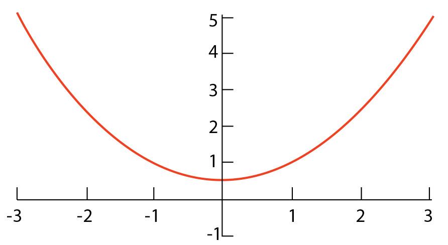
Figure 1
Many times during forming, we’re not forming a true radius,
but instead a parabola.
If you have been following along in recent months with our discussion of bend radius and where it comes from, welcome back. Either way, let’s see how deep this radius rabbit hole goes.
In prior articles I’ve discussed various rules of thumb that operators use on the shop floor to get the job done. These rules can get your inside bend radius prediction close, but you can get even closer.
What Difference Does It Make?
Consider a typical situation where you use the 20 percent rule, which states that an air-bent radius forms as a percentage of the die opening, 20 to 22 percent for stainless steel and about 16 percent for 60-KSI cold-rolled steel, our baseline material.
Say you’re bending soft, 13-KSI aluminum with a 0.984-in. die width and a 0.032-in.-radius punch. Just as a starting point, you calculate the inside bend radius at 16 percent of the die opening to be 0.157 in., though this is for 60-KSI material, so you’ll need to adapt to the material type. Meanwhile, when you calculate to see whether the bend will turn sharp, you find that the minimum radius before your 0.032-in. punch starts creasing the bend line is 0.172 in. Finally, you run a test bend, only to find that the actual radius is 0.170 in.
You have the 0.157-in. radius calculated from the 20 percent rule, then you have the 0.172-in. radius from your sharp-bend calculations. That is a difference in radius of 0.015 in. Not much you say? In this case, the difference when applied to the bend deduction can reach 0.009 in. per bend.
Have you ever built a part with four side flanges with an additional four flanges along the top, only to find that one corner comes up perfect, two corners are marginally satisfactory, and one looks just awful? Why does this happen? A small error in bend deduction caused by discrepancies in your inside bend radius calculations makes a big difference if you want perfect parts the first time.
The heart of any bending operation is the inside radius of the bend. If you can calculate the bend deduction based on the actual results, precision is assured. The only flaw in this theory is that many times during forming we’re not forming a true radius. The shape you are forming may be a parabola, a symmetrical mirrored curve, generally U-shaped when oriented as shown in Figure 1. And the final radius you achieve is the result of springback.
Springback Effects
So how do we predict the most accurate inside radius and the correct bend deduction? To accomplish this manually, the mathematics gets deep in the weeds, so I will not be going there. Rather, we will simply use two different web-based calculators.
The first one is at www.handymath.com. Click on The Complete Circular Arc Calculator. Note that the Width of Arc label in the calculator is the same as the die width, and Angle Subtended by Arc is the same as the included bend angle.
Make sure the calculator’s dimension settings are correct for the data you are using—inches, feet, millimeters, etc. Note that when we click Enter, the answers that we get are purely mathematical and have not been factored for the material tensile strength.
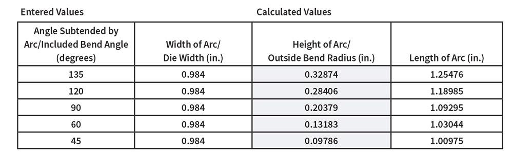
Figure 2
As shown in this calculation from The Complete Circular Arc Calculator at www.handymath.com, as the included bend angle increases, so does the radius (height of the arc).
The information we’re looking for on the calculator is the Height of Arc, which equates to the outside bend radius. Let’s find a value for our baseline, 60-KSI cold-rolled steel, 0.125 in. thick, using a 0.984-in. die width. Please note that we are discussing air forming, so the angle of die will make no difference; it can be a channel, acute, or V die. It’s the width that counts.
First, let’s enter the relaxed angle—that 90 degrees we want to achieve.
These calculations don’t account for springback, though. For our example, we will use a value of 1 degree for springback, which occurs when we have an approximate 1-to-1 relationship of material thickness to inside bend radius. After the punch releases forming pressure, the material springs back 1 degree, so to compensate, we now use a bend angle of 89 degrees included. Again using The Complete Circular Arc Calculator at handymath.com, we enter the following:
Now we take the Height of Arc value for our new bend angle and we plug it into the following formula:
Note that this Height of Arc approach is different from the approach taken in last month’s Bending Basics column, when we used Length of Arc. Last month we calculated an inside radius based on the width of the die opening; this time we’re using a specific radius.
Last month we calculated a radius of 0.136-in., and just now we calculated the inside radius using a different method and came up with 0.170 in.—a difference of 0.034 in. On top of that, if we used the 20 percent rule (again, for 60-KSI cold-rolled steel the radius is calculated to be about 16 percent of the die width), we would calculate an inside radius of 0.157 in.—halfway in between those previous two measurements. These are all different ways in which a radius can be calculated, with slightly different results. But, yes, the rabbit hole does get deeper!
Parabola and Sharp Bends
If you use a punch radius value equal to or less than the minimum sharp-bend radius for air forming a part, you will no longer be creating a radius in the part (for more on sharp bends, see “How an air bend turns sharp” at thefabricator.com). Instead, you will be creating a parabola. You are in effect pulling a different arc length into the die opening.
To predict how this parabola will form, we can turn to another online calculator:https://wwwhad2know.com/academics/parabola-segment-arc-length-area.html. Using the Parabolic Segment Calculator, we enter our outside radius and die width to find the arc length of the parabola. The Height value in this online calculator is equivalent to the outside bend radius, while the Width value is equivalent to the die width:
Here the depth of the parabola (or height of the arc) is 0.201 in. and the arc length for the parabola is 1.0845 in. Remember these values. Returning now to The Complete Circular Arc Calculator at www.handymath.com, we input the arc length at 1.0845 in. and the die width at 0.984 in.
When you do this, you’ll see that the arc height (that is, the outside radius) is 0.195 in., a little smaller than the 0.201-in. outside radius from the previous calculator, which didn’t take into account the parabola effect. Knowing this, we can safely say that the inside radius decreases when a parabola is formed, which occurs when using a punch radius that is less than the minimum sharp-bend radius. Note that the parabola also requires more bend angle to produce the desired relaxed bent angle; we went from an 89- to an 86.68-degree included bend angle, an additional 2.32 degrees of springback. Also note that the inside radius of the part will get no smaller than the punch nose radius.
Angle and Bend Radii
Remember that any change in radius results in a change of bend angle. If we enter the die width and included bend angle on www.handymath.com, we get the results shown in Figure 2.
The results show that when you air form, the radius decreases with the included bend angle (sharp bends excluded).
This bend angle/radius relationship stops at included angles less than 28 degrees included (152 degrees complementary), though the minimum included angle may be larger in material with significant springback.
This is true in part because the minimum press brake punch angle is 28 degrees included. That being said, continuing to close the bend beyond 28 degrees included will result in some form of flattening. The radius will be crushed until the desired bend angle is achieved or a hemming operation is completed. (As a quick side note, for a closed hem the radius is zero and the bend deduction is calculated as a percentage of the material thickness—43 percent under perfect conditions, though it’s a very operator-dependent operation.)
Factoring for Tensile Strength
In the earlier example, we used 1 degree of springback to make the calculations. For 60-KSI mild cold-rolled steel, the average amount of springback is 1 degree or less. What about other materials?
For this, we can predict springback to a reasonable degree of accuracy using the following formula, which requires us to convert all values to metric. Please note that predicting springback is never 100 accurate. However, these formulas do a pretty good job.
First, let’s calculate the springback as if we were working with our 60-KSI baseline material with an inside bend radius of 0.170 in.:
In this example, we’ll round this up to 1 degree. We then can apply the tensile factor for 88-KSI 304 stainless steel.
This gives us 1.46 degrees for 88-KSI 304 stainless. Rounding up, this gives us 1.5 degrees of estimated springback with a 1-to-1 ratio between inside radius and material thickness.
Back to the Calculator
Now that you can estimate springback with some reasonable level of accuracy, you now can compensate for it. To determine the angle you need to compensate for springback, you simply subtract the springback value if you’re working with included bend angles, or add that value if you’re using complementary bend angles. The circular arc calculator on www.handymath.com works with included bend angles (again, labeled Subtended Angle of Arc).
Once you know the inside radius—that is, the actual inside radius that will appear in the finished piece—you can then insert that radius value into your bending formulas (see sidebar).
Conclusion, for Now
By predicting the inside radius correctly, we can accurately calculate bend deductions. Of the several different ways that the inside radius can be predicted, none is perfect, but this one is about as good as it gets. Still, bending has far too many variables to achieve 100 percent accuracy.
It is also an imperative with air forming that the engineer or programmer inform the technician about the tool sets any given bend was designed around. Moreover, the technician needs to realize the absolute importance of using those tools to achieve quality parts.
Next month we’ll cover how to calculate the inside radius of bends where the relationship between the inside radius and the material thickness gets very large—the profound-radius bend. Large-radius bends have issues with die angle, die width, multibreakage, and, of course, very large amounts of springback.
The rabbit hole still has a ways to go, but it’s well worth the journey.
A Review of the Bending Formulas
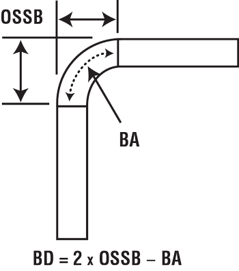
These formulas for bend allowance, outside setback, and bend deduction are well-established, and each value can be used in different ways to calculate the flatblank layout of the part.
Note: The OSSB formula can have the included or complementary bend angle, depending on how you run your flat-blank calculations. For more on this, see “The basics of applying bend functions,” available at www.thefabricator.com.
About the Author

About the Publication

subscribe now

The Fabricator is North America's leading magazine for the metal forming and fabricating industry. The magazine delivers the news, technical articles, and case histories that enable fabricators to do their jobs more efficiently. The Fabricator has served the industry since 1970.
start your free subscription- Stay connected from anywhere

Easily access valuable industry resources now with full access to the digital edition of The Fabricator.

Easily access valuable industry resources now with full access to the digital edition of The Welder.

Easily access valuable industry resources now with full access to the digital edition of The Tube and Pipe Journal.

Easily access valuable industry resources now with full access to the digital edition of The Fabricator en Español.
- Podcasting

In this episode of The Fabricator Podcast, Caleb Chamberlain, co-founder and CEO of OSH Cut, discusses his company’s...
- Trending Articles
1
Capturing, recording equipment inspection data for FMEA

2
Tips for creating sheet metal tubes with perforations

3
Are two heads better than one in fiber laser cutting?

4
Supporting the metal fabricating industry through FMA

5
Hypertherm Associates implements Rapyuta Robotics AMRs in warehouse
