


Press brake bending: A deep dive into springback
Predicting springback isn’t a perfect science, but you can get close
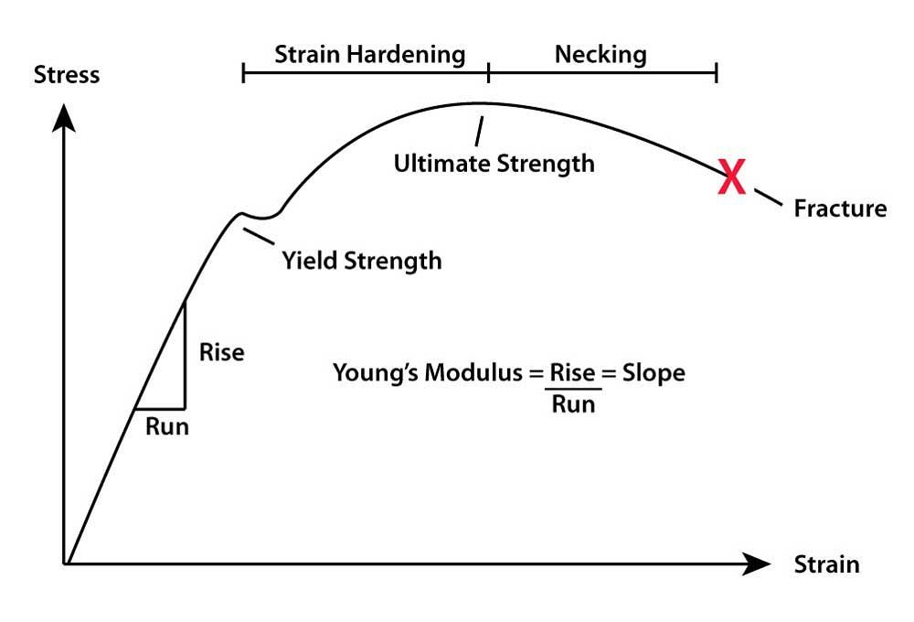
Figure 1
The straight diagonal line on the left of the stress-strain curve shows the elastic zone, where the material returns to its original shape after forming. With enough force, you reach the yield point (or yield strength), after which the material bends permanently to a new shape.
Question: Do you know of any springback calculations for AISI 4130 steel? I need to make a small part with two flanges, one 83 degrees and the other 110 degrees complementary, with an inside radius of 0.118 in.
Answer: Can you find a springback value for a given material? Perhaps, but I’ve never run across a chart or reference book with that kind of information. It would be challenging to compile simply because of the number of variables.
These include the material thickness, bend radius, grain direction, and the bend angle, and this just scratches the surface. Digging a little deeper we find that the K-factor, the material yield strength, and modulus of elasticity (MOE) all play significant roles. Then you have variations in the material’s chemistry, the uniformity of treatments like annealing and tempering, and how well the mill processed a certain batch of metal. These are just a few of the standard variables. It’s much more than just finding a springback value for a particular type of material.
Springback Defined
Springback is a function of elastic and plastic deformation inherent in all sheet metal, plate, plastic, and, for that matter, any material you can bend. Calculating springback is difficult, but not impossible.
To get an accurate calculation, we must include the MOE, yield strength, K-factor, inside bend radius, material thickness, and the included bend angle. You’re probably familiar with some of these, but let’s review them for the sake of those who may not know.
Let’s begin with MOE, and we’re not talking about Mr. Howard or Larry and Shemp. This is serious stuff. MOE, also known as Young’s modulus, determines the ratio of stress and strain during bending and plays a significant role in determining springback.
Imagine material being pushed or forced into an open space between two fixed points, like the top shoulders of a V die. This is strain. As the force is applied, the material will resist. This is stress. As the strain overcomes the stress, we see the material flex—not bend, just bow a little. When the pressure is removed, the material returns to its original shape. This all occurs within the elastic zone, otherwise known as the elastic range of deformation.
In Figure 1 we see that the elastic zone is represented by the straight-line portion of the stress-strain curve. The slope of this line is used to calculate MOE. We find MOE along the stress-strain curve as a function of a material’s elastic range of deformation.
At some point along this line, bending begins and the line starts to curve. This is the proportional limit of the material, or the lower yield point. When reached, the material starts to deform (bend) and will no longer return to flat when released. Put another way, when the material’s proportional limit is reached, the elastic state enters the beginning of its plastic state, or plastic zone, allowing the metal to remain bent. Elastic strain recovery, the engineering term applied to what we refer to as springback, represents a material’s ability (in the plastic zone) to spring back into a new position when released from load.
The higher the value for strain, the greater resistance to forming, and the larger the numerical value for MOE becomes. When any variable value changes, it changes the MOE and corresponding change in springback. For our purposes, the format for MOE is KSI, kilopounds per square inch. 1 KSI is equivalent to 1,000 PSI, or pounds per square inch.
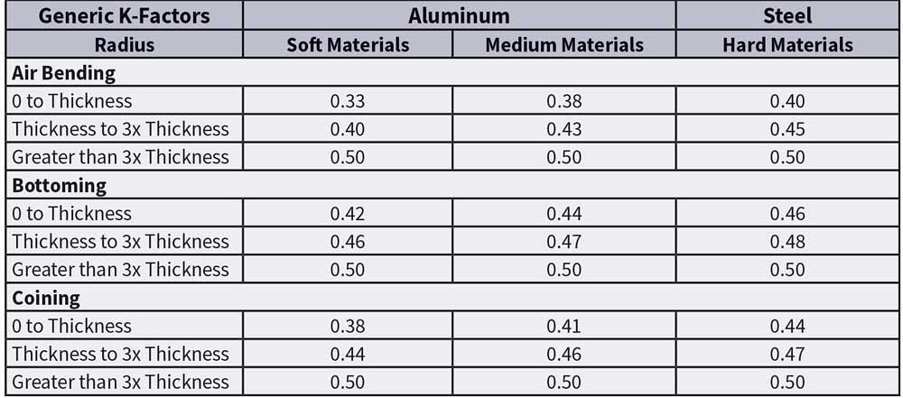
Figure 2
The specific K-factor depends on the material, inside bend radius, and forming method.
Compared to air bending, the effects of springback change when bottoming, which forces a workpiece to a specific angle. The excess pressure of bottoming occurs when the punch nose forces its radius into the material and eventually forces the bend to open up and conform to the die angle, which is almost universally 90 degrees. (This is known as springforward. For more on this, see The hows and whys of springback and springforward.
Coining applies so much force to a bend that the molecules become realigned through extreme pressure, thereby removing 100 percent of the springback from the material. Note that removing springback by this method comes at the expense of the material’s integrity—and possibly permanent damage to the press brake.
Yield Strength
As shown in Figure 1, the yield point on the stress-strain curve is where the plastic state begins. Beyond the yield point we see a brief flattening. This represents elongation, an increase in the strain without an increase in stress, followed by a return of the curve as both stress and strain increase and the work- or strain-hardening begins. In softer materials the brief flattening of the stress-strain curve may not appear but rather just continue to grow until reaching the ultimate tensile strength.
The K-factor
On the outside of a bend, molecules are being pulled apart; on the inside, the molecules are being compressed; and in the center, we have the neutral axis. The neutral axis is a theoretical area within the bend where the material neither expands nor compresses or changes in length. Rather, the neutral axis moves closer to the bend’s inside surface. This shift of the neutral axis is greatly influenced by the inside bend radius, the type of material, and method of forming.
The K-factor is a multiplier used to determine where the neutral axis will be after bending (see Figure 2). This relocation of the neutral axis is the reason that a flat workpiece is always smaller than the sum of the outside flanges and the overall dimension.
Fortunately, we do not need to calculate the values for MOE, yield strength, or the K-factor. These are known values that we can look up and insert into an equation.
Radius bends, those in which the inside radius is greater than 125 percent of the material thickness, will exhibit ever-increasing amounts of springback as the inside bend radius increases relative to the material thickness. These bends increase the amount of strain encountered within the workpiece, which in turn affects the amount of springback.
High-strength steel (HSS) and similar materials with high yield strengths can exhibit springback as high as 60 degrees. This leads us to another issue called multibreakage, or the shrinking of the inside bend radius that occurs when the bend angle exceeds 100 degrees complementary (before forming pressure is released), far enough that the material separates from the punch radius, which compounds springback calculation issues (see Figure 3).
The Equations
It all comes down to looking up and inputting the following information into an equation. Note the format of each input; if these are incorrect, your answer will be too. That said, here are the inputs you need and the equation:
Mt: Material thickness, in inches
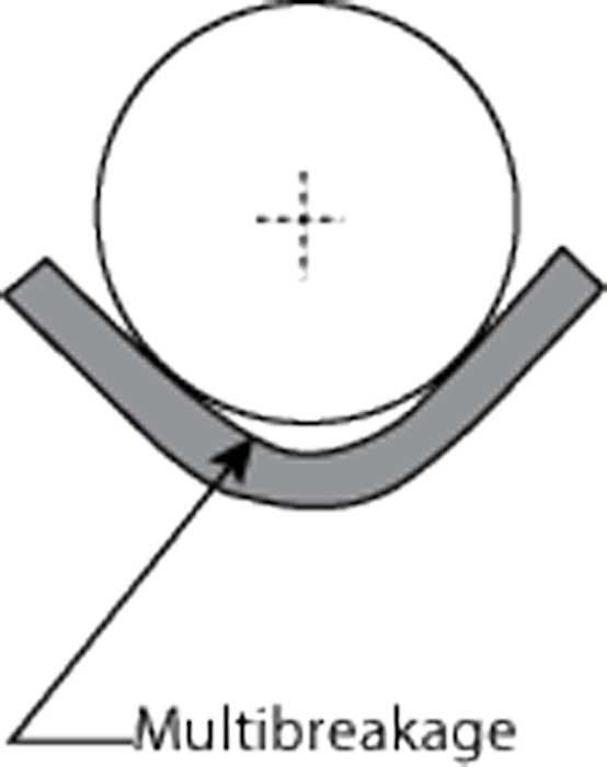
Figure 3
Large-radii bends often require a large amount of overbending to overcome springback. This creates a phenomenon known as multibreakage, where a smaller leading radius forms below the punch.
K-factor: Decimal
Ys: Material yield strength, PSI
MOE: Modulus of elasticity, KSI
Sf: Springback factor
Sd: Springback, in degrees
A: Included bend angle before springback, in degrees
FAi: Final included bend angle after springback, in degrees
Ir: Desired inside radius, imperial decimal
Ra: Radius after forming, in inches
V = (Ir × Ys) / (MOE × Mt × 1,000)
Sf = [4 × (V2) – 3] × V + 1
Ra = Ir /Sf
FAi = [{Ir + (K-factor × Mt)} × A}] / {(K-factor × Mt) + Ra}
Sd = Ir – Fai
First, we look up the yield and MOE data on www.matweb.com for 4130 steel, which is normalized at 1,600 degrees F. We then find the K-factor based on the forming method and material, per the chart in Figure 2. The reader didn’t provide a material thickness, so for this example we’ll just use a thickness of 0.036 in.
Knowing all this, you can either calculate the result yourself, using the following example as a guide, or you can use the online calculator at http://www.theartofpressbrake.com/tools/springback-calculator/.
Mt: 0.036 in.
K-factor: 0.45
Ys: 63,100 PSI
MOE: 29,700 KSI
Ir: 0.118 in.
A: 97 and 70 degrees included
V = (0.118 × 63,100) / (29,700 × 0.036 × 1,000) = 0.006963898
Sf = [4 × (0.0069638982) – 3] × 0.006963898 + 1 = 0.979302289
Ra = 0.118 / 0.979302289
Ra = 0.120493949
For 97 degrees included
FAi = {[(0.118 + (0.45 × 0.036)] × 97} / [(0.45 × 0.036) + 0.120493949]
FAi = 95.23025781
Sd = 97 – 95.23025781
Sd = 1.769 degrees
For 70 degrees included
FAi = {[(0.118 + (0.45 × 0.036)] ×70} / [0.120493949 + (0.45 × 0.036)]
FAi = 68.722
Sd = 70 - 68.722
Sd = 1.278 degrees
So, for a bend angle of 83 degrees complementary (97 degrees included), your springback should be 1.769 degrees. For 110 degrees complementary (70 degrees included), the springback should be 1.278 degrees.
So Many Variables
As good as the math can be, there are still too many constantly changing variables to say that any set of equations for springback will give you a perfect answer. The material will change from bend to bend and from batch to batch. Socan the grain direction. Material coatings can have an effect too. And material properties will not be constant in different areas of a given sheet or workpiece.
Nonetheless, when all these factors are accounted for, we still can predict springback with reasonable accuracy.
About the Author

About the Publication

subscribe now

The Fabricator is North America's leading magazine for the metal forming and fabricating industry. The magazine delivers the news, technical articles, and case histories that enable fabricators to do their jobs more efficiently. The Fabricator has served the industry since 1970.
start your free subscription- Stay connected from anywhere

Easily access valuable industry resources now with full access to the digital edition of The Fabricator.

Easily access valuable industry resources now with full access to the digital edition of The Welder.

Easily access valuable industry resources now with full access to the digital edition of The Tube and Pipe Journal.

Easily access valuable industry resources now with full access to the digital edition of The Fabricator en Español.
- Podcasting

In this episode of The Fabricator Podcast, Caleb Chamberlain, co-founder and CEO of OSH Cut, discusses his company’s...


