


Setting the stage for press brake productivity
Staged bending allows operators to bend more and set up less
Sheet metal fabricators often find themselves with this dilemma: What's more efficient for their customers may create more inefficiency for themselves. In a lean manufacturing world these shops are seeking ways for both parties to maximize efficiency. Bending parts on a press brake offers a prime example of how new techniques make it possible for fabricators to close this efficiency gap.
The call for on-demand parts and short runs can put the efficiency of a fabricating shop to the test. In this environment, a typical shop might run 15 or more different jobs through a press brake on a single shift, and the downtime between each run quickly adds up. Unlike long-run jobs in which economies of scale create greater efficiency, small batch sizes leave little room for error and put unnecessary downtime and other wasteful practices under the spotlight.
Complex parts that require three, four, or more bends are equally problematic for fabricators. Each bend could call for an additional press teardown and setup, adding more downtime. Completing numerous bends also leads to more part handling. This puts a significant toll on a shop's time and manpower and presents some significant roadblocks on a shop's lean journey.
Traditional Solutions Don't Add Up
Fabricators traditionally have had two solutions for these problems. The first is to set up a series of press brakes to create a cell. Each blank travels from press to press and from machine operator to machine operator within the cell. If a part requires four unique bends, it could require four press brakes and four operators. This technique can be effective for long-run jobs, but it's not an efficient use of shop resources for short runs. The use of multiple presses, multiple operators, as well as a large amount of part handling falls short of best practices for lean manufacturing.
Consider a modern computer chassis requiring bends with different angles. The perimeter 90-degree bends are usually coined. Interior bends might require radius tools, and still others might call for offset tooling.
In this situation, a shop has several options. A single operator could set up and tear down one brake with three different tool sets—something that, obviously, would take a significant amount of time. Alternatively, a shop could put three different tooling sets on three separate press brakes. One operator would coin the 90-degree bend and then place the part on a conveyor, which would roll the part over to the second station. Another operator would make the radius bend, then send it on for the offset bend in the same fashion.
Neither option, however, really takes advantage of the concepts of lean, particularly in low-volume applications.
A more efficient solution would involve setting up a series of punches and dies together on a single press brake. With this technique, known as staged bending, a machine operator takes a blank from start to finish through each bending stage on one press. This creates a one-stop process that requires just one machine operator to handle each part only once on a single press brake.
While this sounds like an efficient solution, its traditional application has drawbacks. That's because standard punch and die pairs usually vary in shut height, or the total height of the punch and die when they come into contact (see Figure 1). If all tooling pairs in a press don't have a common shut height, some punches and dies would collide when the press closes.
To avoid this problem, fabricators have used special shims and risers to create a common shut height, placing shim material between the die and the load-bearing surface of the die holder. A shop could purchase shims designed to raise a specific set of tools to the same height, or a fabricator could use a combination of shims.
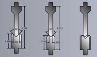
Figure 1 Click image to view largerStandard punch and die pairs vary in shut height, or the total height of the punch and die when they come into contact.
This requires a press brake operator skilled in these specialized techniques—something that's increasingly hard to find. Even with such an operator on staff, this setup technique still can be complex and time-consuming. It nullifies the efficiency gains achieved with staged bending. Furthermore, relying on such a setup specialist is not in line with the lean principle of standardized work. It also creates some organizational headaches: Some shims might work with tool A and B but not with C and D, while others work with A and C but not with D and B, and so on.
The specific bending method also can complicate shimming. Coining and bottoming use matched-set tools, so shimming for common shut heights is straightforward, albeit time-consuming. But with air bending, it can be difficult to determine the exact shut height so that all tools overbend just the right amount to account for springback.
A More Efficient Staged-bending Method
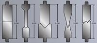
Tooling manufacturers have introduced tooling designed to overcome the longstanding problems associated with staged bending. This tooling has common shut heights built into its design so that a series of punches and dies can be set up in a single press brake (seeFigure 2). This means an operator can arrange a bending setup without the need for risers and shims.
The difference between standard tooling and common-shut-height tooling is in the die design. With standard tooling, shoulder heights are constant but shut heights vary. Shims and risers are required to use multiple tools in the same press brake setup. On common-shut-height tooling, die shoulder heights vary but shut heights are constant, allowing for staged bending without time-consuming procedures (seeFigure 3).
Note that staged bending doesn't happen simply by using sectionalized tooling. Two similar tool sets may be set up next to each other with the same V opening, and air bending with both in one setup may work. However, true staged bending allows an operator to set up starkly different tools next to each other—a 90-degree tool set next to a 30-degree, next to an offset, and so on, all with common shut heights—and perform precision bending.
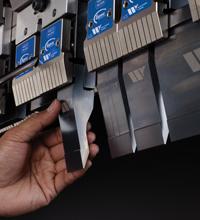
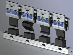
The application of common-shut-height tooling is a straightforward process. A machine operator arranges a series of two, three, or more pairs of punches and dies in one press brake, depending on the bed size and the requirements of the job (seeFigure 4). The operator then takes each blank through the required sequence of bends until complete. Each part is handled only once. Such setups allow shops to "lean out" the bending area. Jobs that may have required multiple brakes and operators might require only one brake and one operator with staged bending.
With this method, fabricating shops can make both American- and European-style press brakes a one-stop destination for all bends that a job requires. Doing so can provide significant lean manufacturing gains by standardizing work, maximizing the use of employees and machinery, and boosting overall efficiency.
Why Staged Bending Hasn't Been Standard
Designing press brake tooling with common shut heights seems like common sense. This begs the question: Why haven't common-shut-height tools been standard all along?
The principal reason lies in the backgauge—the R axis. Before the CNC, the operator set the R axis with a hand crank to a certain point, and that is where those fingers stayed, usually for an entire run. If an operator were to set up a staged-bending operation requiring different backgauge settings, he would have to go around to the back and turn the crank before moving to the next tool. With today's CNC brakes offering multiaxis backgauge control, the fabricator need only program those backgauge angle changes into the controller, and the operator can bend from one stage to the next, no hand-cranking required.
Some shops still have those pre-CNC brakes with hand cranks. And while no tooling will ever make these machines as flexible and efficient as their CNC cousins, the older machines still can benefit from common-shut-height tools. Overall, die shoulder heights in common-shut-height tooling vary little and so require little, if any, backgauge adjustment. There are significant exceptions, of course. A 30-degree tool next to other tools, for instance, would present some backgauge issues for manual machines. But for many applications, as long as the backgauge is set to a midpoint, the material still will hit the backgauge pad, even if the die shoulder height is slightly shorter or taller.
About the Authors
About the Publication
subscribe now

The Fabricator is North America's leading magazine for the metal forming and fabricating industry. The magazine delivers the news, technical articles, and case histories that enable fabricators to do their jobs more efficiently. The Fabricator has served the industry since 1970.
start your free subscription- Stay connected from anywhere

Easily access valuable industry resources now with full access to the digital edition of The Fabricator.

Easily access valuable industry resources now with full access to the digital edition of The Welder.

Easily access valuable industry resources now with full access to the digital edition of The Tube and Pipe Journal.

Easily access valuable industry resources now with full access to the digital edition of The Fabricator en Español.
- Podcasting

In this episode of The Fabricator Podcast, Caleb Chamberlain, co-founder and CEO of OSH Cut, discusses his company’s...


