


Editor-in-Chief
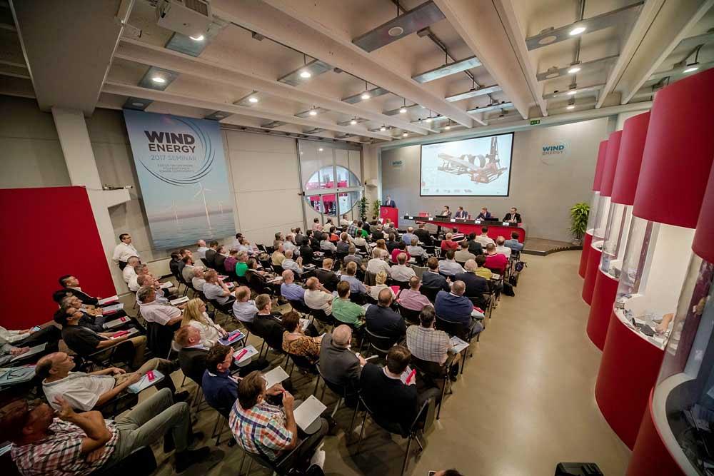
Figure 1
Fabricators from all over the world participated in the 2017 Wind Energy Seminar in Cesena, Italy, hosted by DAVI.
Wind energy isn’t going to just blow away. Fabricators from all over the world learned that at the 2017 Wind Energy Seminar at the Cesena, Italy-based home of DAVI, a manufacturer of plate rolling equipment (see Figures 1 and 2).
With all the recent talk in the U.S. about deriving more oil from shale exploration and attempts to reinvigorate the coal industry, you may not have noticed the news of the first domestic offshore wind farm coming online in 2016. The five massive wind towers sitting about 15 miles off the coast of Block Island, R.I., are expected to add ample power to the state’s power grid, ultimately cutting homeowners’ electricity rates and decreasing the need for fossil fuels to generate power.
As an example of the potential impact that the country’s first offshore wind farm is making already, consider that municipal officials in Block Island closed the island’s traditional source of power, a small, diesel-fueled power plant, in May during a four-month test run of the wind turbines. They are now attached to Rhode Island’s mainland power grid thanks to a connection to the wind farm. The Block Island Wind Farm is rated at 30 megawatts, which should be more than enough to power every Block Island home for the foreseeable future. With the island’s power plant closed, residents will no longer have to rely on the burning of 1 million gallons of diesel each year for power.
That’s a pretty impressive start for a country that, frankly, lags behind the world when it comes to offshore wind energy production. The U.S. has seen its share of onshore wind towers being built over the past decade, but the real potential for power generation lies offshore, where the wind blows harder and more consistently than inland winds. Some experts believe that if the U.S. were to fully exploit offshore wind energy, we could generate 4,000 gigawatts per year, which is more than four times the current U.S. electricity-generating capacity.
According to industry observers, however, if U.S. fabricators want to be a part of this expanding market, they are going to need bigger machines. These offshore wind towers are an entirely different fabrication when compared to their onshore cousins. More specifically, the offshore towers require a foundation anchoring system not used by onshore units.
Teemu Tolonen, an applications manager, wind tower production, PEMA Welding Automation, provided fabricators with an idea of just how large these wind towers are getting. (PEMA was a sponsor of the seminar along with DAVI, HGG Group, and Lincoln Electric.)
Onshore towers can have section diameters as big as 1.5 to 5 meters (5 to 16.4 feet) and thicknesses from 15 to 60 mm (0.59 to 2.35 in.). The section weights can reach 100 tons. Additionally, some of these tower sections require conical bends, about a 4- to 6-degree angle differentiation from the bottom of the section.
Tolonen said that even onshore towers are evolving in size. Some midsized towers are built with increasingly taller sections to minimize the number of sections, which obviously increases the weights of those individual tower components.
So how does this compare to the offshore towers? Diameters for those wind tower sections are typically 3 to 7.5 m (9.8 to 24.6 ft.), and the wall thicknesses of the plate used to roll those “cans” are from 18 to 80 mm (0.70 to 3.15 in.). The sections can weigh up to 300 tons.
Another unique aspect of offshore towers is that they have to be anchored in some way to the sea floor. They require a base on which to sit, unlike their onshore counterparts, and that foundation must be able to withstand the fury of the sea. Therefore, the foundation has to be wider than the tower sections that sit atop it.
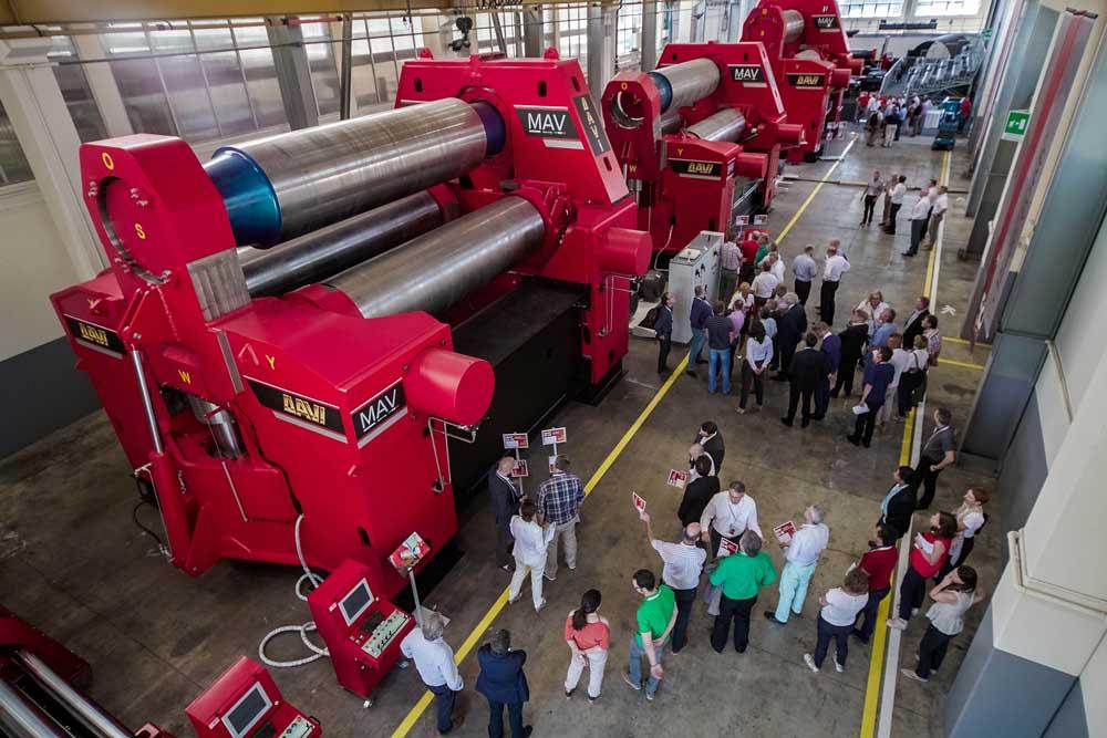
Figure 2
Fabricators attended the seminar to learn about the latest technology developments aimed at making the fabrication of offshore wind turbine sections and foundations more efficient.
The most common type of foundation is the monopile, according to Tolonen. These are cylindrical in nature, like the tower sections, but larger and thicker. A typical monopile section has a diameter between 5 and 8 m (16.33 and 26.25 ft.) and a thickness between 40 and 140 mm (1.58 and 5.51 in.). These sections can reach a weight of up to 800 tons. With the latest designs, the join between the monopile and the transition pieces is conical and the fabrication process, comprised of several conical sections welded together, has become even more complex.
To show that this type of fabrication was possible, PEMA demonstrated an assembly line for helping to align and fit up cylindrical and conical shells into tower sections or foundations (see Figure 3). PEMA personnel were able to fit up and tack weld two shells in less than 30 minutes. Also, as part of its presentation to fabricators, PEMA discussed its latest special machinery designed to bevel, weld, and fit the flanges in large-diameter cylindrical sections.
Tolonen added that by 2020 extra-extra-large monopiles might be required for the latest generation of wind turbines, which could be rated for as much as 10 megawatts of power. These sections conceivably could have a diameter of 12 m (39.33 ft.) and weigh up to 1,800 tons each.
The other predominant type of foundation is a jacket-style base, which the five wind turbines in the Block Island Wind Farm sit on. These jackets comprise support legs that are a lattice of pipe. This interlaced structure is fabricated from several thermal-cut pipes that are then welded together to create the supporting structure.
U.S. fabricators are much more familiar with this type of offshore foundation as it has been frequently used in oil and gas applications. Even in this type of fabrication, however, evolution is putting a strain on fabricators’ capabilities. Tolonen said that pipe diameters are getting smaller, compared to monopile foundations, yet wall thicknesses are increasing.
As far as the future, designers are looking at floating concepts or hybrid designs, where a tower might not only have a wind turbine, but also a base that would be able to convert wave activity to energy. One fabricator mentioned a base design for shallower waters in which the foundation is a large, wide shape, much like a bathtub, which is filled and heavy enough to keep the tower erect.
The task of producing these large tower sections sounds daunting, but these fabricating shops have not been without some technological help over the years. For instance, DAVI introduced its first tower rolling system in the late 1990s. Today the company has more than 250 systems in operation around the world, according to company officials.
DAVI used the seminar to unveil its latest development related to wind tower fabrication, an automated line with a patent-pending plate feeding system that is designed to simplify the forming of cones. The machine’s control software automatically calculates the movements and the position of the system’s hydraulic guides, which allows the plate to remain in the perfect geometric position as it is being fed into the rollers. The precision feed also ensures the correct rotation during the continuous cone forming process.
Stefano Santoni, DAVI’s Wind Energy Business Unit manager, said that the software is designed to be user-friendly and calculates the guide positions for each different cone dimension. This can be very helpful for operators without a lot of plate rolling experience.
“This unique and innovative plate feeding system ensures that a consistent but limited specific pressure is applied on the plate to generate a continuous rotation for cone forming. At the same time, it preserves the integrity of the plate bevel while the high dynamic forces of the rolling process occur,” Santoni said.
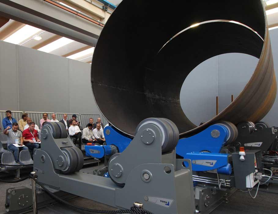
Figure 3
PEMA Welding Automation officials demonstrate how automated material handling equipment can be beneficial for fitting up extremely large cylindrical and conical shells, such as those found in wind tower sections and foundations.
“This system can help to meet 100 percent of the tolerances required in conical rolls,” he added. The system is designed to deliver conical angles up to 8 degrees.
Santoni stressed that the most important aspect of the new DAVI plate rolling system is a continuous guiding mechanism that prevents damage to the weld prep work done on the plate edge. This means that once the rolling operation is complete, a fabricator does not need to rework bevels damaged by the high pressure required to generate the continuous plate rotation necessary for cone forming.
DAVI officials gave seminar attendees an opportunity to see how the new cone rolling machinery worked. With the conical plate situated on a conveyor (see Figure 4), the control software instructs the hydraulic guides to grip the plate along the edge and feed it into the four-roller setup. The plate proceeds until it is automatically squared against the outside roller. Once squared, the plate reverses, and the plate’s end is situated beneath the top roller and the bottom roller. The initial pinch initiates and the prebend occurs.
The prebend on the leading edge of the plate is important as it gives a flat section that the rolls can grab. With a four-roll system, that flat part is minimized. The plate processing system is designed to prebend the leading edge with maximum accuracy and minimum distortion, according to the company.
During the initial prebending phase, the infeed table elevates along with the entry side support and side roll. These actions are fully synchronized to keep the plate completely flat during the prebending phase and avoid any counter moment that could lead to distortion.
Santoni said that this feature is very important in maintaining the integrity of the cone rolling process. Other systems are known to lift the plate only with the entry side roll, generating a counter bending moment that could lead to heavy distortions on the final radius.
Once the prebend is done, the feeding process begins. The hydraulic guides grip the plate and maintain optimized pressure and plate position through the rolling process.
Once the can is about 25 percent complete, the side support elevates to hold the can as it curves. When the can reaches the halfway point of forming the final round shape, the vertical support becomes more important as it maintains the can’s proper shape and prevents the plate from collapsing because of its own weight.
During the final moments of the rolling process, the entry side support elevates to hook the initial rolled plate portion. This helps to keep the lead portion of the plate roll from possibly overlapping with the last portion to be formed.
Once within the grasp of the rollers, the plate is moved in reverse to complete the alignment of the cylinder. At this point, edge alignment in preparation for tack welding can occur to ensure that the final shape and tolerances are maintained.
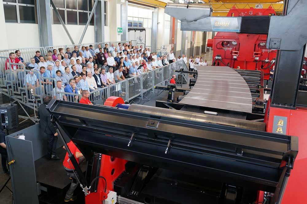
Figure 4
Fabricators look on as DAVI personnel demonstrate the company’s new, patent-pending plate feeding system and its ability to form conical shapes.
Santoni held a demonstration of the high-productivity plate roller on the seminar’s second day. He mentioned that rolling a cone using older “advanced systems” might take about 10 to 15 minutes, and using a completely manual system without accessories could take more than an hour. During the demonstration, a DAVI operator was able to position and square the plate, prebend, roll a complete cone, and align the two leading edges in about six minutes.
Santoni has indicated that iCone© software, developed by DAVI, plays a huge role in the success of rolling very large and heavy offshore components. (The software can work with plate up to 140 mm [5.51 in.] thick and weighing up to 80 tons.) In this case, the software automatically calculates the position of the hydraulic guides that intermittently rotate the plate while cone forming.
Attendees also had the chance to see Lincoln Electric’s submerged arc welding technology that maximizes material deposition at increased production speeds and HGG’s automated 3-D cutting systems that pull their job instructions from building information models. Tools such as these, PEMA’s latest in heavy-duty cylinder rotation systems for automated welding systems, and the new DAVI plate rolling technology are going to help fabricators keep up with the bigger and bolder designs for offshore wind towers and foundations.
“The machines of today have nothing to do with the machines of yesterday. These past few years we have re-engineered and redesigned our complete line of angle rolls and plate rolls,” said DAVI President Orazio Davi. “These machines will help the fabricators with their future work.
“It should be noted, however, that achieving these results has only been possible because of tight cooperation with our most experienced end users.
A deep cooperation between machine manufacturers and end users will always be the key for success.”
DAVI—Promau Group, www.davi.com
HGG Group, www.hgg-group.com
PEMA Welding Automation, www.pemamek.com
Lincoln Electric, www.lincolnelectric.com


The Fabricator is North America's leading magazine for the metal forming and fabricating industry. The magazine delivers the news, technical articles, and case histories that enable fabricators to do their jobs more efficiently. The Fabricator has served the industry since 1970.
start your free subscription
Easily access valuable industry resources now with full access to the digital edition of The Fabricator.

Easily access valuable industry resources now with full access to the digital edition of The Welder.

Easily access valuable industry resources now with full access to the digital edition of The Tube and Pipe Journal.

Easily access valuable industry resources now with full access to the digital edition of The Fabricator en Español.
In this podcast episode, Brian Steel, CEO of Cadrex Manufacturing, discusses the challenges of acquiring, merging, and integrating...


