


Senior Editor
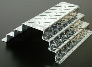
Figure 1: This tread plate was bent using a rotational die, which eliminates workpiece positioning and angle problems commonly found when a traditional V die hits diamond treads. Photo courtesy of Fab Supply Inc.
Tread plate and perforated sheet have bending characteristics that baffle and frustrate. They just won't hold still. They shift slightly, go askew. They act as if they have a life of their own, and in a sense they do. They want to bend at their weakest point, the path of least resistance—and that may not be at the intended bend line.
To help matters, fabricators may need to look beyond typical air bending with a punch and V die. Though bending alternatives vary, they have one commonality: They clamp down to ensure the workpiece stays where it should.
Tread plate and V dies rarely get along. For one, air bending with a punch and V die may produce tread plate with inconsistent flange lengths. "It has to do with the way the material draws down into the V die when it's being formed," said John Wold, president of Fab Supply Inc., Addison, Ill. "If the drawing action is consistent, the flange length will be consistent. It's just that simple."
Tread plate with inconsistent angles and flange lengths wreak havoc in the welding department. "This means your welders are spending a lot of time blacksmithing those parts prior to welding them," Wold said. "People may not attribute those costs to the press brake department, but they should. Eliminating inconsistencies in your flange lengths and angles will result in a major increase in throughput in your welding department."
The root of the issue is at those single points of contact at the lead-in radii—the two bottom points of contact in a three-point bend. Since the diamonds, or treads, rarely contact the die's lead-in radii the same way for every bend, the results typically vary. Like bending speed bumps, diamond treads drawing down into the V die can get hung up on that lead-in edge, causing one side of the bend to draw down into the V more than the other side. The unequal drawing creates a flange slightly longer or shorter than it should be.
Material thickness gauging has its own idiosyncrasies when it comes to tread plate, sources said. Depending on where the diamonds hit the lead-in radii, the operation may act as if the material is thicker or thinner, and such variation can affect the resulting angle.
Consider a material and brake set up for 3⁄16-in. material thickness, as measured from the top of the diamond to the bottom of the material, but only 1⁄8 in. as measured from the flat portion between the diamonds to the bottom side of the sheet. During air bending the workpiece contacts the V die at two points, at the lead-in radii. If those points contact the material at the diamonds' apex, the metal thickness is 3⁄16 in. But it's also likely the points could contact the metal between the diamonds, changing the measured material thickness from 3⁄16 to 1⁄8 in. That change can alter the resulting angle.
In other circumstances, coining to avoid angle variation might be an option—but not for tread plate, which can be marred or crushed as it's squeezed between the punch and die. A die coining such material won't last long either.
Tread damage remains a problem even when air bending. As Wold explained, "Due to the extremely concentrated load, the lead-in radii actually can dig into the diamonds, damaging the material and creating a very sharp, dangerous, and unacceptable edge."
Irregular tread patterns—without straight lines of tread diamonds—complicate the situation even more, and again it's because of those two single contact points with the V die. Consider a plate with a bend line that goes diagonal to the tread pattern. A view of the brake bed head-on reveals serious problems. On the left a diamond apex may contact the lead-in radius, and on the right the metal may hit the radius between diamonds. This shoves the workpiece off-kilter as soon as the punch starts to bend. "The workpiece is askew, no longer parallel to the die surface," explained Carl Michelsen, vice president of engineering for Polyurethane Products, Addison, Ill. This, he said, can lead to serious bending inconsistencies.
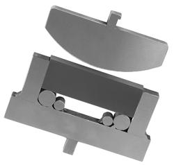
Figure 3: Urethane pads provide a surface that supports tread plate and perforated sheet during the bend. The descending punch clamps the material in place. Photo courtesy of Acrotech Inc.
Tools that clamp and hold the workpiece during forming frequently eliminate these difficulties. One option is the rotational die, which has rotating elements in front of and behind the bend line (see Figure 1 and Figure 2). The die starts flat and, as the punch descends, rotates into a V shape. The flat contact surface and descending punch provide intimate workpiece contact and act as that all-important clamping action.
Secured between the punch and rotational die surfaces, the metal has minimal if any draw-down during the bend. Thickness variation isn't an issue either, because the die surfaces are wide enough so that they cover multiple treads, making it impossible for the die to contact the surface between the diamonds. The tread plate also can't get caught on the lead-in radius because, well, the die has no lead-in radius. The die contact has changed from two points (as in a typical V die) to a broad surface.
Urethane die pads also provide a surface, eliminating inherent complications with the V die. This setup involves a steel punch and a urethane pad on the bottom in a steel retainer with a tang that can be inserted onto the press brake. The urethane pad flows up and around the workpiece on either side of the descending punch. The urethane acts almost like a bladder of hydraulic fluid. It starts flat and forms with the workpiece. Because it has a wide forming surface, the die pad allows the punch to clamp the metal in place during the bend (see Figure 3).
The life of urethane die pads varies greatly, sources said. As with most other technologies, it depends on the application. "Die life depends on the material and how far you are penetrating into the material, and what kind of radius bend you are trying to perform," said Andy Oliver, president of Acrotech Inc., Lake City, Minn.
Another option is to step away from the press brake entirely and go the metal folding route. On folding systems, most of the part sits on the table behind the bend tooling. Hold-down tools clamp the workpiece, and the folding beam swings up (and also down on bidirectional folders) a specified amount to make the bend.
Like the specialty press brake tooling, the folding system helps mitigate workpiece positioning issues, thanks to the hold-down tools that clamp the material in place before folding (see Figure 4). The folding beam then applies the force to make the bend. According to a paper published by RAS Systems Inc., Peachtree City, Ga., "While the folding beam moves up to the required angle, there is almost no motion between the tool and the material surface."
Put perforated material between a punch and a die, and the amount of material the tools contact can change from bend to bend, depending on the holes' shapes and where they are in relation to the bend line. The descending punch will follow the path of least resistance, to where there is less metal to bend, toward the middle of the perforated holes and away from the bridges of metal between the holes.
"It won't repeat itself time and time again, depending on where those perforations are," said John Hughes, president of Best Brake Die, Crestwood, Ill. "The material will always try to bend where it has been weakened first." This in turn causes inaccuracies in flange length.
Air bending such material takes finesse. Under excess bending pressure, the holes will stretch and distort, creating sharp edges. Occasionally, Wold said, bottoming or coining can minimize the problem.
Problems with bend angles crop up as well, again because the amount of material under the punch can vary. If the punch contacts mostly free space (holes) and less metal, the metal will spring back less; if it contacts more metal and less free space, the part springs back more. This can make predicting springback a bear.
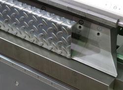
Figure 4: Folding systems clamp tread and perforated material in place before bending. Once the material is clamped into position, the folding beam swings up to perform the bend. Photo courtesy of RAS Systems LLC.
As Hughes explained, custom press brake tooling setups can compensate for this phenomenon. A punch slightly taller in the solid metal area creates a greater overbend, compensating for the differential in springback between perforated and solid sections. He added, though, that small design changes often can eliminate such tooling complications. Moving perforations away from the bend line can make bending more consistent. For this reason, Hughes said, engineers should design out the problem whenever possible.
As Polyurethane Products' Michelsen explained, fabricators also should check with their perforated sheet supplier. A perforation operation with dull punches can create burrs, and subsequent leveling can work-harden material excessively, which makes the perforated metal susceptible to cracking when bent. Choosing a supplier that produces clean perforations makes life in the bending department a lot easier.
Material type also plays a major role—and the greater the tensile strength a material has, the more challenging bending becomes. As Rick Wester, vice president at RAS Systems, explained, "Aluminum is easier [to bend accurately] than mild steel. And stainless steel, well, that just has a mind of its own."
As with tread plate, tooling setups that clamp perforated material before bending can overcome a lot of problems. Using rotational dies, the punch secures the perforated sheet as it initiates bending, just as with tread plate.
Metal of extremely high tensile strength may move regardless, "but in most situations, as long as the clamping pressure is adequate to overcome the resistance, your bend will be accurate," Wold said.
A rotary tool set (a specialty tool set not to be confused with rotational dies) also may help in certain circumstances, particularly for large workpieces (see Figure 5). "Rotary dies eliminate workpiece whip-up," Hughes explained. If workers must bend a short flange at the edge of the large sheet, the majority of the sheet whips upward as the punch descends. The rotary die clamps the workpiece while the flange is being formed.
Essentially, the rotary tool makes the press brake function like a folding machine, though the brake tool can bend flanges that are only so long. But like a folding system, the press brake rotary tool allows the flange to bend and the rest of the panel to remain stationary and horizontal.
This also means operators need not follow up the sheet during bending, eliminating the possibility of back-bending, a problem especially common when bending large, thin sheet. If operators do not properly support the sheet during forming, the sheet's weight will cause it to deform in the opposite direction of the intended bend. "As challenging as flanging large panels can be from a back-bending perspective, perforated sheet can be even more difficult because it is less rigid," Wold said.
Urethane pads are another option. The pads allow the punch to act as a clamp as soon as it starts to bend the metal. With products such as perforated lighting fixtures requiring large-radius bends, bump bending can be a challenge. As Michelsen explained, urethane tools help greatly in this arena. The urethane fully supports the material during the radius bend and thus eases what can be an extremely difficult forming operation (see Figure 6).
Folding machines also handle perforated metal well, sources said. The machine's hold-down tools clamp the workpiece so it can't move during the bend, counteracting the metal's tendency to bend at its weakest point, at the middle of the perforations.
Figure 5: Rotary tool sets may be an alternative for bending perforated material, especially large workpieces. The setup allows the brake to bend the flange while the rest of the workpiece remains stationary. Image courtesy of Fab Supply Inc.
As RAS Systems' Wester explained, folding systems today can predict the amount of resistance required to fold a flange to the desired angle—a benefit when bending infamously unpredictable perforated material. "When working with perforated material, it comes back to how much metal you have versus free space," Wester said. "The angle is easier to control the more metal surface you have. The more air opening you have, the more difficult it can be."
He added that modern folding systems account for this variation. "Now the operator steps on the foot pedal, and the bending beam swings up to 10 degrees and then back to home. It has just sensed the resistance in this flange to be folded and now knows the exact crowning needed to fold this flange to the programmed position."
In folding, the swing beam folds the flange, and excess bow (deflection) in that beam can alter the final bend angle. So on modern folding systems, sensors inside the beam measure deflection during initial degrees of folding beam movement. Using this information, the CNC adjusts values in the program and activates a crowning system in the folding beam to compensate for beam deflection. This way, the beam can swing just the right amount to produce the desired angle.
Wester added that in folding, the beam—not the tooling—determines the degree of bend, which can help when dealing with the difficult-to-predict springback of perforated sheet. If an operator sets up to bend an angle to 90 degrees, in the initial teach mode he may underbend to 88 degrees, and then measure the workpiece. He would enter that information into the controller, which would then instruct the machine how much farther to move the beam to produce that precise 90-degree bend.
The right tools make bending tread and perforated metal much easier. Which tools to use depends, as always, on the situation. Fabricators must weigh myriad factors, including workpiece size, material type, thickness, and the amount of perforated and tread plate material flowing through the bending department.
Regardless, the common thread remains. Such material must somehow be held securely to be bent accurately. If the workpiece moves unexpectedly during the bending cycle, achieving accurate bends will continue to be an uphill battle.
Best Brake Die Inc., 13428 S. Kolmar, Crestwood, IL 60445, 708-388-1896, www.bestbrakedieinc.com
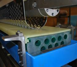
Figure 6: A urethane pad provides support during large-radius bending of perforated sheet. Photo courtesy of Polyurethane Products Corp.


The Fabricator is North America's leading magazine for the metal forming and fabricating industry. The magazine delivers the news, technical articles, and case histories that enable fabricators to do their jobs more efficiently. The Fabricator has served the industry since 1970.
start your free subscription
Easily access valuable industry resources now with full access to the digital edition of The Fabricator.

Easily access valuable industry resources now with full access to the digital edition of The Welder.

Easily access valuable industry resources now with full access to the digital edition of The Tube and Pipe Journal.

Easily access valuable industry resources now with full access to the digital edition of The Fabricator en Español.
In this episode of The Fabricator Podcast, Caleb Chamberlain, co-founder and CEO of OSH Cut, discusses his company’s...


