


Time for new press brake tooling
How dies and punches affect the inside bend radius—Part I
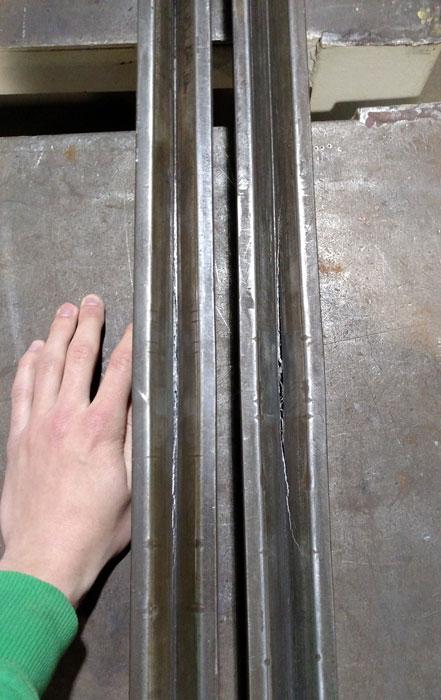
Figure 1
These split dies have seen better days.
Question: I am an intern at a fabricator, and I’m working with our new press brake operator and optimizing our bending processes. When I started a few months ago, neither the operator nor I had much (or any, in my case) experience with press brakes.
I absorbed as much information as I could from thefabricator.com. Your articles have helped me understand how bending sheet metal works. Using equations from your articles, I was even able to come up with a way to determine the bend line on some of the round stock we bend. But I can tell I have a long way to go yet, and I’m still confused about a couple of points.
I was told we have 0.125-in. punches and dies along with 0.25-in. punches and dies, and this means we can do either a 0.125- or 0.25-in. inside-radius bend. We achieve the dimensions we are seeking, for the most part, but our tooling is very old, and we had two of our 0.125-in. dies split open (see Figure 1). We are looking for new tooling, but I want to be sure of what we need.
We mostly bend to 90 degrees, and to achieve this we bottom-bend the part. I understand this takes about five times more tonnage than air bending and is much harder on the punch and die, so I would like to avoid this if possible.
If we move to air bending, should we acquire dies with an angle of 85 degrees? And is the bend radius of the die unimportant when air bending, and all that matters is the punch and the size of the V opening?
Also, what is the best way for us to get our 90-degree bends while maintaining the inside radius dimension so that our postbending dimensions come out the way we want?
Answer: To start, let me comment on the die photograph you sent. I can’t begin to tell you the number of shops I have visited over the years where the tools they were using looked like these. Even without the splitting damage, it is obvious these dies have seen better days; by anyone’s standard, they’re completely worn out.
Just from the picture I can see seriously worn spots that are inches long, and areas where the die opening is wider than it should be when compared to the rest of the die. This damage occurs when tools are overloaded. If you don’t bottom-bend or coin, your chances of getting a consistent bend are small, if not outright impossible.
From the looks of your two dies, there’s a good chance the ram of the press brake suffers from ram upset, a condition where the ram and/or the bed of the press brake are permanently deflected (see Figure 2).
Because you have been bottoming for some time, it may be in your best interest to run a magnetic base with a dial indicator down the length of the ram and bed. See if the indicator climbs as you reach the center, and check for ram upset. If you find it in either the ram or bed, seek medical treatment for your press brake, or have the machine put down. It’s not worth the fight. So yes, you certainly need new tooling, and, depending on the damage done, you may also need new press brakes.
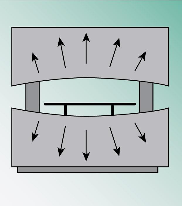
Figure 2
Ram upset can permanently deflect the bed and ram of the press brake.
Radius Does Matter
Regardless of method—air bending, bottoming, or coining—the inside bend radius is at the heart of precision sheet metal bending. Without it we will not be able to calculate the values for K factors, bend allowance, outside setbacks, and bend deductions. The inside radius of a workpiece matters—big time.
First, let’s clarify some terminology. The punch radius is obvious: It’s the radius of the punch tip. Die radius usually refers to the radius of the die shoulder on either side of the die opening. Based on your question, I’m going to assume that you’re referring to the radius at the bottom of the V die.
When air bending or bottoming, a sharp corner at the bottom of the V is still technically a “radius.” However, you may be coining, in which case you would be using a die with a noticeable radius at the bottom of the V. That radius should match the outside radius of the bend, like how a stamping die works.
You stated that you have a 0.125-in.-radius punch and a 0.125-in. radius at the bottom of the die. With this, you are trying to produce a 0.125-in. inside radius in materials from 0.108 to 0.375 in. thick. You’re also trying to produce a 0.25-in. radius with a 0.25-in. punch nose radius and 0.25-in. radius at the bottom of the die.
We need to consider one more factor here: your outside bend radius. You calculate the outside bend radius by adding the inside bend radius to the material thickness. A 0.125-in. inside bend radius in 0.125-in.-thick material will have an outside radius of 0.25 in. (0.125 + 0.125 = 0.25).
Let’s consider your application again (see Figure 3). If you bend 0.125-in.-thick material with a 0.125-in. punch nose, you’ll achieve a 0.125-in. inside bend radius and a 0.25-in. outside bend radius—which you’ll be pushing into a die with only a 0.125-in. radius at the bottom. How’s that working out?
This is an extreme example of what happens when the die width and radius at the bottom of the V are too small for the job. I’d be willing to bet that the look on the outside of your bends gets a little ugly.
How a Radius Forms
Just how the radius is created varies greatly with the bending method. If I use a punch with a nose radius equal to the inside radius I want to achieve, then I can bottom-bend or air-form the part. This is a “perfect” bend.
In an air bend, what matters most is the width of the die opening, as the radius will be floated as a percentage of that width. The percentages vary by material type. The correct die width will give you the bend radius you need. (For more on this topic, you can review How the inside bend radius forms.
The second-most important consideration in air forming is the punch nose radius. You do not want a radius on the punch nose to be larger than the natural radius floated in the part, and you do not want a punch nose radius less than what’s known as a sharp bend, or the minimum inside radius that’s possible without creasing the center of the bend. For more on this topic, check out “What makes an air bend sharp on a press brake?” and “How an air bend turns sharp,” both archived at thefabricator.com.
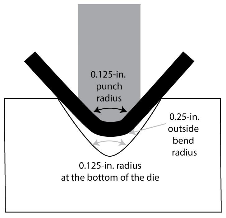
Figure 3
This coining setup will lead to problems. The radius at the bottom of the die should not be smaller than the outside bend radius.
Depending on your desired inside radius, you can use these concepts to pick the appropriate die opening and punch radius for the job. The closer you can get the punch nose radius to the naturally floated radius, the more consistent and stable the bends will become, both dimensionally and angularly.
Air Bend Tooling Considerations
If you’re air bending, know that the included die angle, die radius, and the radius at the bottom of the die have no effect on the floated inside radius of the workpiece, which again is a function of the die width.
That said, if you will be air forming, the 85-degree dies you mentioned are a good choice, as long as their widths produce your desired inside bend radii in your workpieces, and they can handle the required forming tonnage. Know, however, that bottoming cannot be performed or even attempted on these tools. Acute dies are meant solely for air forming. Combining any acute-angle die with the tonnage pressure of bottoming would create so much side thrust on your die that it would split your tool down the middle.
How do you select the correct styles and profiles for your new punch and die sets? That will be the topic of next month’s column.
Tooling Is a Consumable
I have watched many a fabricator buy a new, state-of-the-art press brake only to continue to use the same old beat-up tooling and outdated methods—then question why their new, state-of-the-art press brake isn’t living up to expectations!
Press brake tooling should always be viewed as a consumable item; it’s long-lasting, for sure, but it does not last forever. It wears out. The amount of extra time your operator will spend attempting to correct for issues directly related to worn-out tooling will far surpass the costs of new, high-quality tooling.
Along with supervisors, managers, and executives (who may not want to spend the money), operators and technicians are just as culpable in hindering the adoption of new tooling, bending methods, and machines.
“We’ve always done the job with that old tool.”
“We can’t do the job without that old tool.”
“We’ve always used it, and it can’t even be mounted into the new press brake.”
Occasionally a job may require a special tool, but you can use adapters (traditional planed to precision, or precision to traditional planed) to fit it on a new press brake. It often boils down to human nature and having to move out of our comfort zones.
As an industry, our mindset must change: New tooling makes positive things happen!
Steve Benson is a member and former chair of the Precision Sheet Metal Technology Council of the Fabricators & Manufacturers Association International®. He is the president of ASMA LLC, steve@theartofpressbrake.com. Benson also conducts FMA’s Precision Press Brake Certificate Program, which is held at locations across the country. For more information, visit www.fmanet.org/training, or call 888-394-4362. For more information on bending, check out Benson’s book, theArtofPressBrake: the Digital Handbook for Precision Sheet Metal Fabrication, ©2014, available at www.theartofpressbrake.com. The author’s latest book, Bending Basics, will be available soon at the FMA bookstore, www.fmanet.org/store.
About the Author

About the Publication
subscribe now

The Fabricator is North America's leading magazine for the metal forming and fabricating industry. The magazine delivers the news, technical articles, and case histories that enable fabricators to do their jobs more efficiently. The Fabricator has served the industry since 1970.
start your free subscription- Stay connected from anywhere

Easily access valuable industry resources now with full access to the digital edition of The Fabricator.

Easily access valuable industry resources now with full access to the digital edition of The Welder.

Easily access valuable industry resources now with full access to the digital edition of The Tube and Pipe Journal.

Easily access valuable industry resources now with full access to the digital edition of The Fabricator en Español.
- Podcasting

In this episode of The Fabricator Podcast, Caleb Chamberlain, co-founder and CEO of OSH Cut, discusses his company’s...
- Trending Articles
1
How to set a press brake backgauge manually

2
Capturing, recording equipment inspection data for FMEA

3
Tips for creating sheet metal tubes with perforations

4
Are two heads better than one in fiber laser cutting?

5
Hypertherm Associates implements Rapyuta Robotics AMRs in warehouse
