


What makes an air bend sharp on the press brake?
It’s the relationship between the punch nose radius, forming tonnage, and the material’s strength
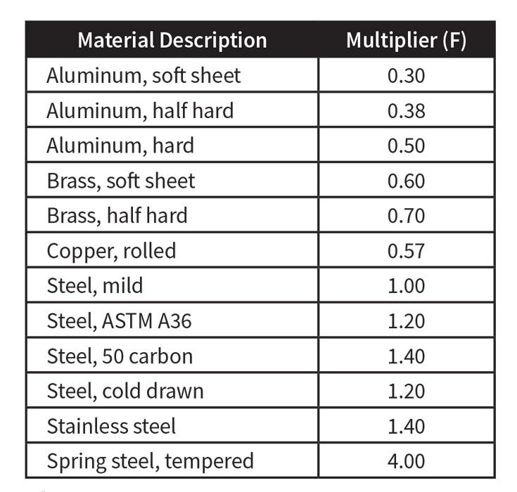
Figure 1
This chart shows different multipliers to use when calculating punching tonnage for different materials.
Question: I found your article about the 63 percent rule helpful. In your article, you give the example of bending 1⁄4-in.-thick steel with different punch radii.
I decided to play with the formula a bit and used 20-gauge cold-rolled steel with a 1⁄32-in.-radius punch for my calculations. This is a great punch and material combination, but according to the way I understand your article, it isn’t because my punching tonnage is less than the tonnage required to form.
For example, the land area is 0.375 in. in a foot, multiplied by a material thickness of 0.036 in., and then multiplied by 25. This gives us 0.338-tons-per-foot punching tonnage. According to my bending chart, it takes 3.1 tons per foot to form 0.036-in.-thick cold-rolled steel with a 0.25-in. V die. Does this mean that for thin materials, you will always be creating a ditch and losing bend consistency and stability? Or am I using your calculations incorrectly?
The only factor that I don’t understand is where the 25 comes from in your formula. Is that related to material thickness or a constant? I would like to understand this topic well, as I want to know the deeper theory behind what I do on a press brake.
Answer: You are on the right track, but we need to clarify a few points. So let’s start from the beginning. First, what does the 63 percent represent? That’s the estimated percentage of the material thickness at which the bend turns from minimum inside radius to a sharp bend. This is based on ASTM A36 mild cold-rolled steel with a tensile strength of 60 KSI. That material is as middle-of-the-road as it gets. That is the baseline material upon which our calculations are based.
Air forming is our baseline method of forming. Why? It’s because of the low tonnages involved compared to bottoming or coining, and it is now becoming the prevalent method of forming. Bottoming and coining are fundamentally different from air forming as the radius is “stamped” rather than “floated” across the die opening, as in air forming. (For more on this, see “How the inside radius forms” from the June 2013 issue, archived at www.thefabricator.com.)
Note that 63 percent is a rule of thumb, and as with any such rule, there will be exceptions. What truly determines the point at which a bend turns sharp is the relationship between the punch nose radius, the tonnage required to form, and the tensile strength of the material.
Walking Through the Steps
Stepping through your example, you’re forming 0.036-in. cold-rolled steel with a 1⁄32-in. punch over a 0.25-in. die width. With that information in hand, the first step is to determine the forming tonnage, or the tonnage required to bend the workpiece:
(575 × 0.001296) / 0.25 = 2.9 tons per foot
to form the material
That’s pretty close to the 3.1 tons per foot figure you found in the chart.
Step two, we determine the land area. This is the interface between your 1⁄32-in. punch nose and the surface of the material.
Land area = 0.03125 × 12 = 0.375
Step three, we determine the punching tonnage, or piercing tonnage. We are looking for the minimum force necessary to pierce the material’s surface. In a punching situation, this is the point where the rollover would stop and the shearing begin. For our purposes in press brake bending, the punching tonnage is the point at which the press brake’s punch tip starts to penetrate and crease the material surface. For this, we use a standard tonnage calculation formula used for the punching process, incorporating a material multiplier, as shown in Figure 1.
Unlike forming tonnage, punching tonnage actually uses 50,000-PSI-tensile-strength material as a baseline (as described later). This requires us to use a material multiplier, giving us a punching tonnage a little higher than you originally calculated:
Material thickness × 25 × Material multiplier
Punching tonnage = 0.375 × 0.036 × 25 × 1.2 = 0.405 ton
Regardless, it is correct to say this is a sharp bend; it takes more tonnage to form than to pierce, and variations in bend angle and dimension will be the result. From years of personal experience, I can assure you that if you are truly air forming with a 1⁄32-in.-radius punch in 0.036-in.-thick material, you are experiencing some level angular variation.
What I’m describing here is neither inconsistent with modern theory nor the root cause of the variations that appear in the forming operation. Once created, the crease is simply, for lack of a better description, an amplifier of the inconsistencies within the material, like variations in grain direction, hardness, and thickness. These and similar variables are the root cause of angular variations from workpiece to workpiece.
The 25 Constant
So where does the 25 in this formula come from? It is a constant that represents the average shear strength of 50-KSI mild cold-rolled steel. To quote Tooling Around the World, a Wilson Tool publication from February 2013:
× 50,000 lbs./in.2 ÷ 2,000 lbs./ton
Land Area × Thickness x 25
or
Punching Force (tonne):
Land Area × Thickness × 345 N/mm2 ÷ 9,806.65 N/tonne
Perimeter × Thickness × 0.0352
Because this 50-KSI mild steel was once the most commonly used material, it became the material all others were compared to, such as stainless steel. The tensile strength of stainless is about 75,000 lbs./in.2 (or 518 N/mm2). Compared to mild steel, stainless will take 1.5 times more force to shear.
Please note the tonnage to break the material surface is only a reasonably precise estimate, as this formula was not intended for press brake applications. However, the numbers are close enough for our purposes.
Sharp Bends
Should you find yourself with a sharp bend—which your example is—it is best to avoid it. Avoiding a sharp bend whenever possible will make your bends more consistent and stable from workpiece to workpiece.
To do that means increasing the radius on the nose of the punch to the point where the punching tonnage (which we’ll also call the piercing tonnage) exceeds the forming tonnage.
Thin Material and Bottoming
That being said, let’s walk through the last two paragraphs using the data already calculated from your question. First, when working on this scale, there is a very fine line between air forming, bottom bending, and coining—a few thousandths of an inch, in most cases. This could mean that if your bends are stable, odds are you are bottom bending.
In air forming, your inside radius is based on and developed as a percentage of the die width (the opening), which I refer to as the “20 percent rule”—a title only, as the percentages vary by material type. For our baseline material, ASTM A36, that value is 16 percent.
Being universally accepted, this concept means that for a 0.250-in. die width, the floated inside radius will be 16 percent of that width, or 0.040 in. So unless you are bottoming with your 0.032-in. punch nose radius, 0.040 in. will be the inside radius of the bend.
But our theory also states, and our data has confirmed, that the tonnage required to form (2.9 tons) was greater than the tonnage required to pierce the surface of the material (0.405 ton). This means that even though the punch radius and material thickness are about as close to “1-to-1” as it gets, the 1⁄32-in. punch nose is still creasing the inside radius of the bend, though on a very small scale and at a point very close to the radius on the punch nose. So for all intents and purposes, it is amplifying the material variables.
So how large does the punch radius need to be to avoid a crease? To find out, you can do a little mathematical trial and error with the punching tonnage formula, replacing the punch radius value with a larger value until the punching tonnage exceeds the forming tonnage:
Punching tonnage = (Punch radius × 12) × Material thickness × 25 × Material factor
In this case, the minimum inside radius for your original question would be 0.2238 in.:
Forming tonnage = (575 × 0.001296) / 0.25 = 2.9 tons per foot
Realistically, you probably would not do this and stick to forming this example using the 0.032-in. nose radius. So what does this do for you then? Not much. It simply explains why sometimes when bending this basic 1-to-1 material thickness-to-radius relationship, you can still have dramatic swings in bend angle rather than having the stable angles we would normally expect from bend to bend.
Soft Material
Remember, forming tonnage is based on ASTM A36 60-KSI cold-rolled steel. If a material has a different tensile strength, you need to incorporate a material factor.
Let’s look at another example that incorporates thicker and softer O-series aluminum: 0.125 in. thick with a tensile strength of 13 KSI.
The first step is to find the material factor for the forming tonnage formula. We will estimate this value by dividing its tensile value by the 60-KSI value of our baseline material: 13/60 = 0.21, or 21 percent. In this case, we will be using a 0.984-in. die width.
All three of these values are then inserted into our basic forming tonnage calculations as follows:
[(575 × 0.015625) / 0.984] × 0.21 = 1.917 Tons per foot
Now it’s on to the punching tonnage. Starting with a 0.125-in. punch nose radius, we first calculate the land area value and then the punching tonnage. Because this material is not listed in Figure 1, we calculate the multiplier by comparing it to our 60-KSI baseline: 13 KSI/60 KSI = 0.21. Knowing this, we start our calculations.
Land area = 0.125 × 12 = 1.5
Punching tonnage = Land area × Material thickness × 25 × Material multiplier
Punching tonnage = 1.5 × 0.125 × 25 × 0.21 = 0.984 ton
So it will take approximately 0.984 tons of punching force to begin breaking the surface of the material. All this shows how the relationship between the punch nose radius, die width, and the material’s tensile strength determines where a “sharp bend” occurs. In this example, the material surface’s ability to resist the force being applied to it ends at 0.984 tons. If you then were to apply the 1.917 tons of pressure required to form the material with the calculated land area, you are going to crease the part.
Next, bearing in mind that sharp bends are a function of the material and not the punch nose radius, we calculate the minimum inside radius for our given piece of material. As we did in the previous example, we first perform several trial-and-error math problems, replacing the inside radius with a progressively larger value until the tonnage to form is less that the tonnage to pierce the material.
In this soft material, we find that it isn’t until we reach a radius value of 0.250 in. that we acquire our minimum inside bend radius.
Land area = 0.250 × 12 = 3.0
Piercing tonnage = Land area × Material thickness
× 25 × Material multiplier
Piercing tonnage = 3.0 × 0.125 × 25 × 0.21 = 1.968
With a 0.250-in. radius, the tonnage or force required to pierce the surface is 1.968 tons, based on the land area. The tonnage to form the material is 1.917 tons, which means no piercing or thinning of the material will occur.
Now we’ve determined that 0.250 in. is the minimum bend radius. So what is the naturally floated inside radius for this air bend? For bends in which the radius isn’t approaching a sharp bend, we usually estimate the floated radius as a percentage of the die width, per the 20 percent rule, with 16 percent of 60-KSI cold-rolled steel as our baseline. Comparing our 13-KSI material with the baseline, that percentage will be only about 3 percent, making our estimated floated radius very small indeed, and significantly less than where the bend turns sharp.
In this case, we calculate the floated radius based on our rule of thumb about where the bend turns sharp—at 63 percent the material thickness of our baseline 60-KSI mild steel. Again, the percentage will be much lower for our soft 13-KSI material. Because the material is so much softer, it will carry a much smaller inside radius then our baseline material would, just as stainless would carry a larger inside radius in the part.
To determine it, we run a comparison with our baseline material: 13 KSI/60 KSI = 0.21; 0.21 × 0.63 = 0.1323. Put another way, 13 KSI is 21 percent of 60 KSI, and 21 percent of our baseline 63 percent is 13 percent. So according to this, the minimum radius is 13 percent of our 0.984-in. die opening: 0.984 × 0.13 = 0.127 in.
This estimate is less than our previously calculated 0.250 in.; and as we calculated earlier, any radius that’s smaller than 0.250 in. would cause our punch tip to penetrate and crease this soft material before forming it. In this case, we would choose our larger-value “minimum” 0.250-in. radius to calculate our bend deductions. With a punch nose radius of 0.250 in., to avoid creasing and creating a sharp bend, the material will take on the larger radius of the punch nose, less the springback factor, or the slight opening of the angle and radius as the material is released from pressure.
When working with sharp bends in air forming, you need to use the minimum radius value for your bend allowance (BA) and the bend deduction (BD) calculations. Why? Because if you use the wrong radius value—for example, any punch nose radius less than the minimum inside radius—your calculations will be off.
Applies to Air Bending Only
Remember, this discussion does not apply to bottom bending or coining. In these cases, the tool nose radius is forced into the workpiece, stamping it into the material being formed, so the material’s inside radius takes on the inside radius of the punch nose, less the springback factor. The springback factor represents the slight opening of the inside radius of the bend as it is released from pressure. For more on this, see “The Hows and Whys of Springback and Springforward” from May 2014, archived at www.thefabricator.com.
Best Practices
Try to select a punch nose radius as close as possible to the naturally floated radius or minimum radius when air bending. The wrong inside radius will change your bend allowance, which will make your outside setbacks, and ultimately your bend deduction, incorrect; the resulting formed part will be either too big or too small. Remember, a bend deduction error of just 0.010 in. over four bends means that your notch or other features will be in the wrong location by 0.040 in.
Overall, try to avoid forming parts to their sharp bend radius, or at the very least, do not use the sharp bend value in your calculations. Instead, use the minimum or floated bend radius.
If you use the minimum radius value, instead of the sharp bend radius value, for your bend deductions, you will find that it leads to much better quality over time. You also may see a dramatic reduction in labor costs, as operators will no longer be fighting as many bend angle issues and correcting for dimensional errors—saving you hours of handworking parts back to a sellable condition.
Conclusion
We’re just scraping the tip of the iceberg here. Besides the sharp and minimum bend radii, there are two more bend classifications: a perfect bend and a radius bend. For more on these, you can check out the Bending Basics series, “A grand unifying theory of bending,” published from September through December 2015 and archived at thefabricator.com.
The bottom line is this: As you approach the minimum radius/sharp divide, you start to form a crease at the center of a floated radius, which in turn will result in variations in the bend angle and, ultimately, your linear dimension variations. The sharper that you make this crease (the smaller the land area), the greater the variations will become—which ultimately causes quality to suffer.
Steve Benson is a member and former chair of the Precision Sheet Metal Technology Council of the Fabricators & Manufacturers Association International®. He is the president of ASMA LLC, steve@theartofpressbrake.com. Benson also conducts FMA’s Precision Press Brake Certificate Program, which is held at locations across the country. For more information, visit www.fmanet.org/training, or call 888-394-4362. F or more information on bending, check out Benson’s book, theArtofPressBrake: the Digital Handbook for Precision Sheet Metal Fabrication, © 2014, available at www.theartofpressbrake.com. Steve Benson’s latest book on press brake bending, published by FMA, will be available soon.
About the Publication

subscribe now

The Fabricator is North America's leading magazine for the metal forming and fabricating industry. The magazine delivers the news, technical articles, and case histories that enable fabricators to do their jobs more efficiently. The Fabricator has served the industry since 1970.
start your free subscription- Stay connected from anywhere

Easily access valuable industry resources now with full access to the digital edition of The Fabricator.

Easily access valuable industry resources now with full access to the digital edition of The Welder.

Easily access valuable industry resources now with full access to the digital edition of The Tube and Pipe Journal.

Easily access valuable industry resources now with full access to the digital edition of The Fabricator en Español.
- Podcasting

In this episode of The Fabricator Podcast, Caleb Chamberlain, co-founder and CEO of OSH Cut, discusses his company’s...
- Trending Articles
1
AI, machine learning, and the future of metal fabrication

2
Employee ownership: The best way to ensure engagement

3
Steel industry reacts to Nucor’s new weekly published HRC price

4
Dynamic Metal blossoms with each passing year

5
Metal fabrication management: A guide for new supervisors
