


President & CTO
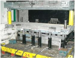
Figure 1: Multipoint variable binder-force control is available for stampers for use in die tryout, as well as production.
Splits, wrinkles, and springback are problems that the stamping industry deals with every day. The advent of finite element analysis (FEA) simulation and engineered draw beads, along with CNC machining, has greatly improved the efficiency of the die design and construction processes, but forming defects still pose challenges during die development and production stamping.
The increasing use of lightweight, high-strength alloys to meet stringent fuel efficiency and safety standards in the automotive industry has further complicated the job of building tooling for deep-drawn parts. In addition, price pressure stemming from the use of these relatively expensive materials demands significant reduction in scrap rates in production.
Multipoint variable binder-(blank holder) force control can help stampers meet these challenges, and the technology now is ready to be deployed both in die tryout and production (see Figure 1).
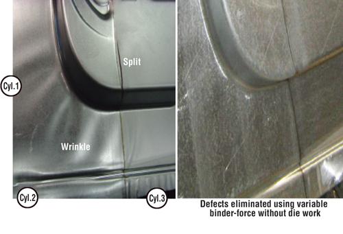
The concept of variable binder-force control is intuitive; if a split is imminent, the binder force at the location of the split is reduced, allowing more local material flow and thus eliminating the split. Conversely, if a wrinkle is forming, the binder force is increased locally to stretch out the wrinkle. For springback reduction, the binder force can be increased at the appropriate location at the end of the stroke.
The ability to change binder force both spatially and during the stroke has been shown to reduce die tryout time by 60 to 80 percent based on shop floor data. The die geometry is not changed, eliminating repeated changes to the draw bead or die face that could do more damage than good.
While the general impression is that special segmented binders are required in variable binder-force systems, extensive testing in tryout and production facilities has shown that regular ring binders—even steel ones with reinforcing struts—have sufficient flexibility to control material flow into the die.
A typical variable binder-force system (see Figure 2) consists of a set of hydraulic cylinders, a hydraulic unit, pressure and stroke sensors, servo valves, and a computer to control the pressure in the hydraulic cylinders.
The key to implementing variable binder-force technology is to have a system that can be commanded to provide local binder force in very precise steps during the press stroke.
Common System Architecture for Tryout and Production. Successful implementation of variable binder-force technology requires that the optimal binder tonnages be determined during tryout with a sufficiently precise system.
For parts such as automotive door inners, a system with 12 to 15 computer-controlled hydraulic cylinders, each with a capacity of 0.5 to 25 tons, as well as a stroke of 7.5 inches independently commanded in 0.25-inch increments with 0.5-ton steps, is effective. For larger parts with high-strength steels, 20 cylinders with a capacity of 0.5 to 30 tons may be required to provide optimal spatial coverage and generate the force required for springback reduction. Figure 3 shows examples of tonnage variations in two independently controlled cylinders.
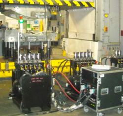
Figure 4: The hydraulic unit and control electronics are visible as part of a variable binder-force system installed in a die tryout facility.
Depending on the application, a variable binder-force system can be designed using hydraulic cylinders with the same dimensions as standard nitrogen gas springs and used as an alternative to them. With a portable hydraulic control unit, such a configuration works well for prove-out and prototype applications, allowing the cylinders to be moved to different presses and used with multiple dies.
For production, a variable binder-force system can be packaged into a rolling bolster. Cushion pins transfer the force from the cylinder to the binder, and the cylinders are designed for repositioning based on the die pin configuration; however, die setup time is minimized if the system is used for a family of parts with a standard pin configuration.
The pin pattern is on a 9- to 12-in. grid for a typical system. Using an appropriate design for the cylinders and bolster plate can minimize the difference in height compared to a standard rolling bolster. Packaging the system in a rolling bolster allows it to be used in a backup press with similar dimensions.
System Retrofittable Into Mechanical Presses. Many stamping facilities use mechanical presses for high-volume production, while programmable cushions typically are found in hydraulic presses.
Since the hydraulic pressure in the cylinders is developed by compression of the hydraulic fluid by the press ram, the control system for a variable binder-force system is quite simple for a hydraulic press, as the ram speed is relatively constant. In a mechanical press, however, the ram speed rapidly decreases from a high value to zero during the stroke, resulting in variable compression of hydraulic fluid in the cylinders.
To generate the desired binder force in each cylinder during the stroke with the ram speed variation of a mechanical press, an advanced computer control system is required. The controller must be able to adapt to multiple press speeds without tuning or calibrating, as presses may run at different speeds for different jobs. Commercial variable binderforce systems that run in production mechanical presses have been tested at rates of up to 17 strokes per minute (SPM).
User-friendly Operator Interfaces. With an intuitive interface, typical operators with basic computer skills can be taught to use the system in less than an hour. For production, the system should be secure to prevent unauthorized changes to tonnage settings.
Simple Installation and Maintenance. The system design should take into account installation and maintenance requirements for both tryout (see Figure 4) and production. For tryout, the unit should allow easy reconfiguration in multiple presses for use with several different dies. For production, packaging the system within a rolling bolster allows for quick die change and minimal changes to the existing press line.
To ensure consistent performance, the design’s primary focus should be reliability, with all components designed for high-shock and -vibration environments. Using standard, off-the-shelf hydraulic components allows for in-house maintenance, while system software issues can be resolved via remote access.
With a variable binder-force system, the tonnage in cylinders 1 and 2 was raised, while the tonnage in cylinder 3 was reduced to a low value 0.5 in. off bottom. This allowed the material to flow from the right and heal the split.
The use of variable binder force to reduce springback has been studied extensively using FEA simulation and in experimental tests.1,2,3 While high binder forces reduce springback, a constant high binder force all around the binder and through the stroke can cause tearing. A variable binder-force system can use lower binder forces at the beginning of the stroke to ensure that the strains do not reach critical levels and raise the binder force at the end of the stroke to get the deformation required to eliminate springback and side-wall curl.
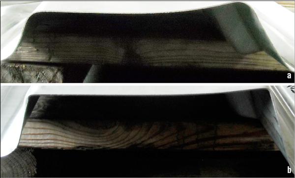
For more complex parts, different binder-force profiles can be used at different locations. For example, Figure 6a shows the level of springback in a part made of DP 780 high-strength steel (HSS) using constant binder force, while Figure 6b shows how springback can be reduced using variable binder force. To make the part in Figure 6b, the binder force was kept at a high level on one side, and on the other side, it was kept low at the beginning of the stroke and then raised to a high level for the last 1 in. of travel.
One of the most common problems in production stamping is process variability, caused by such factors as lubricant buildup, die wear, temperature changes, and material property variations. Often a part that was running fine suddenly starts wrinkling or splitting, leading to high scrap rates and production downtime.
Recent studies show that standard tonnage monitor signals can be used to identify conditions such as lubricant buildup and material thickness changes in real time (see Figure 7), and that these signals can be used to adjust the binder forces to maintain part consistency.4,5,6
With its high control of local material flow and reduced scrap rates, variable binder-force technology offers a powerful solution for challenging HSS stamping applications.
Notes
1. M. Sunseri, J. Cao, A.P. Karafillis, and M.C. Boyce, “Accommodation of Springback Error in Channel Forming Using Active Binder Force: Control Numerical Simulations and Experiments," Journal of Engineering Materials and Technology, Vol. 118 (1996).
2. B. Kinsey, J. Cao, and S. Solla, “Consistent and Minimal Springback Using a Stepped Binder Force Trajectory and Neural Network Control,’’ Journal of Engineering Materials and Technology, Vol. 112 (2000), pp. 113-118.
3. V. Viswanathan, B. Kinsey, and J. Cao, “Experimental Implementation of Neural Network Springback Control for Sheet Metal Forming," Journal of Engineering Materials and Technology, Vol. 125 (2003), pp. 141-147.
4. Y.S. Lim, R. Venugopal, and A.G. Ulsoy, “A Multi-Input Multi-Output Model for Stamping Process Control," in proceedings from ASME International Symposium on Flexible Automation, sponsored bv ISFA, Atlanta, June 23-26, 2008, pp. 1-8.
5. Y.S. Lim, R. Venugopal, and A.G. Ulsoy, “Improved Part Quality in Stamping Using Multi-Input Multi-Output Process Control," in proceedings from American Control Conference (ACC), sponsored by American Automatic Control Council, St. Louis, June 10-12, 2009, pp. 5570–5575.
6. Y.S. Lim, R. Venugopal, A.G. Ulsoy, “Multi-Input Multi-Output (MIMO) Modeling and Control for Stamping," Journal of Dynamic Systems, Measurement, and Control, Vol. 132 (2010).


The Fabricator is North America's leading magazine for the metal forming and fabricating industry. The magazine delivers the news, technical articles, and case histories that enable fabricators to do their jobs more efficiently. The Fabricator has served the industry since 1970.
start your free subscription
Easily access valuable industry resources now with full access to the digital edition of The Fabricator.

Easily access valuable industry resources now with full access to the digital edition of The Welder.

Easily access valuable industry resources now with full access to the digital edition of The Tube and Pipe Journal.

Easily access valuable industry resources now with full access to the digital edition of The Fabricator en Español.
In this episode of The Fabricator Podcast, Caleb Chamberlain, co-founder and CEO of OSH Cut, discusses his company’s...


