


Senior Editor
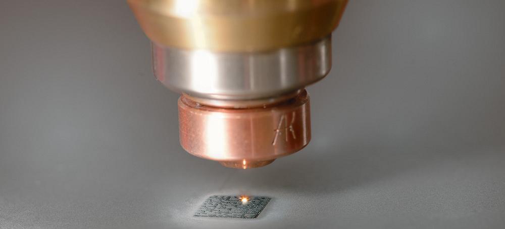
Figure 1
A laser etches a QR Code® onto the sheet. The code can be scanned to identify the part and, in certain press brakes, to bring up a bending program. Photo courtesy of Bystronic Inc.
Modern forming technology has eased kit-based part flow. New press brakes and other bending machines boast changeover times of just a few minutes, sometimes seconds. Complicated staged bending arrangements can be programmed and simulated offline, minimizing or sometimes eliminating tool changes between pieces. Small lot sizes just aren’t a problem like they once were.
Unlike batch processing, with rows and rows of identical parts to a sheet, kit-based nesting calls for disparate parts to be placed on one nest, and downstream bending machines can form all the parts needed for a subassembly in short order. This gets a fabricator closer to that ideal of single-piece part flow.
Of course, if you put too many different parts on a nest, the person offloading the parts has a puzzle on his hands, and he doesn’t have much time to solve it. Which piece goes where? It’s not an impossible puzzle to solve, but it is prone to error. A shop that has moved to kit-based part flow probably has less WIP buffers, which means there’s less room for error.
At the cutting machine offloading area, how do you minimize the chance for error when you’ve increased complexity by nesting dozens of different parts on a sheet? Moreover, regardless of what type of part flow an operation has, and whether nests contain different or identical parts, fabricators now are producing more parts faster. How can a shop keep track of it all?
Industry has tackled the issue from several fronts: One focuses on nesting and automation, the other on parts marking and labeling.
Nesting software has advanced in a big way in recent years, and those advances have brought better material utilization. Some nesting systems use the computing power of multiple remote servers and more powerful optimization algorithms—the cloud—to design a tighter nest with a higher material yield. Cloud-based nesting engines run on complex algorithms that really couldn’t be run on a PC. “You get better results and faster results,” said Frank Arteaga, head of product marketing at Bystronic Inc., Elgin, Ill. “It goes beyond basic common-line cutting, and it uses clustering.” As the name suggests, this technique clusters parts together, finding common cut lines between many part profiles. The result: an extremely sparse skeleton.
Modern optimization algorithms can change the situation. Now the programmer may be able to fit an additional complete kit onto a nest where parts are dynamically grouped to form clusters, virtually eliminating the material webbing between the parts. This results in high material yield. And because parts in a kit are clustered together with no webbing between, the task at the offload station becomes much simpler.
Arteaga added that a related strategy involves material handling automation in laser cutting. Say a programmer nests a job on several sheets of different thicknesses—say, 0.25 inch, 0.1875 in., and 0.125 in.—all of which belong to one assembly. In an automated situation, the operator can designate the machine to cut the sheets and then place them all in one offload shelf in a tower. This presents a single kit of parts to downstream operations, which can be easier to identify, transport, and organize.
Imagine two similar parts are sent to a press brake cell in a kit, one in which the flange bends up, and another in which the flange bends down. An operator may bend a flange the wrong way, but this time he does it only in the pieces of the kit, not to an entire batch. That’s a big benefit to kit-based processing. Still, preventing the error from occurring in the first place requires something else, and this is where marking and labeling come into play.
Some operations now have small printers to create labels that stick to blanks coming off the cutting machine. But a person still needs to be there to put on the label, and the wrong label on a similar-looking part can cause serious problems. Two options get around this: One is marking parts in the cutting machine itself (see Figure 1); the other is automated labeling, in which labels are made and affixed before a sheet enters the cutting envelope.
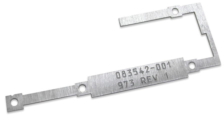
Figure 2
A scribe tool was used on the punch press to mark the part number and revision on this workpiece. Photo courtesy of Mate Precision Tooling.
In the punching arena, special tools that stamp or scribe part identification into sheets have been available for years. Parts marking in sheet metal has its origins with typesetting. “The early marking tools borrowed from this,” said Scott Tacheny, special applications engineer at Wilson Tool International®, White Bear Lake, Minn. “But it had to be a fixed phrase, word, or a number. Otherwise, it just wasn’t easy to use.”
The next logical step, he said, was to put the alphabet in a multitool arrangement that could fit the entire alphabet, 0 through 9, and a few symbols. It’s basically a typewriter for sheet metal, making a permanent indentation in the material surface.
For many high-product-mix operations, scribe tools eventually became more popular, Tacheny said, because the scribe simply followed a geometry path in the shape of a letter—or any other shape, for that matter—so programming it was less complex (see Figure 2). Scribe tools also can act as a dot matrix printer, creating text or an image as a series of dots.
Other tools can “write” on sheet with an ink marker, leaving text or other marks that can be rubbed off if needed downstream (see Figure 3). “It’s a permanent marker, but it can be wiped off using solvents commonly found in the shop,” said John Ripka, application technician at Mate Precision Tooling, Anoka, Minn.
He added that most varieties of programming software can import fonts from Windows® and elsewhere, “and then basically apply any kind of text you want. Once you apply the text to the part, you can apply the tooling to it, be it drag scribing or dot matrix marking, and typically the software will create the code, depending on your machine and which type of marking you’re going to create.”
For years cutting lasers have been able to etch markings onto the sheet. Today some lasers can be programmed to etch part identification and even QR Codes onto the parts themselves (see Figures 1 and 4). Once the parts reach forming, the operator scans in the code, which brings up the part program and all the pertinent information about the job. The user can customize it with specific work instructions and notes.
“This gives you so much more information than you would normally get with an etched part number,” said Arteaga. “Within that QR Code you can have not just the part number, but the revision, revision dates, and link you to a URL or a path to designate where the file is stored. So when you scan it in at the press brake, it will automatically pull the bend program into the press brake.”
He added such marking also helps with traceability. “If you suspect a part wasn’t made correctly, you can trace that part back.”
If a fabricator needs a nonpermanent mark, or is working with sheet metal with protective films, etching may not be a practical way to go. Nevertheless, such material sometimes needs some kind of part identification.
“The coating can make it difficult to differentiate one part from another,” said Al Bohlen, vice president and general manager at Mazak Optonics Corp., Elgin, Ill. For instance, one part may have a hole in it, and a similar part may not. On an uncoated sheet, that hole stands out. But with a protective coating, the hole doesn’t stand out as much. Hence, it’s easy to understand how the part might be misidentified.
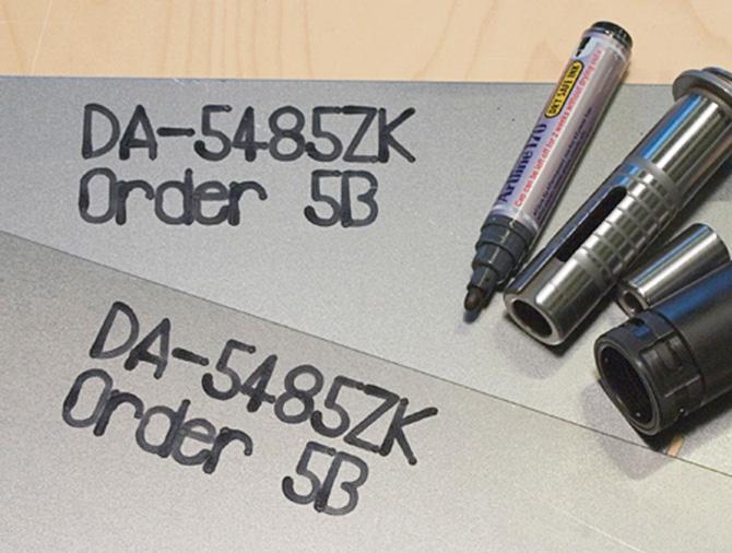
Figure 3
A punch press’s ink marker tool applied these part identifications. Photo courtesy of Mate Precision Tooling.
Manually applying sticky labels remains an option, but the person applying the labels still can misidentify a part. As Bohlen explained, “Fabricators have asked, ‘Is there a way you could automate applying a sticky label on parts in the nest? And can it be configurable?’”
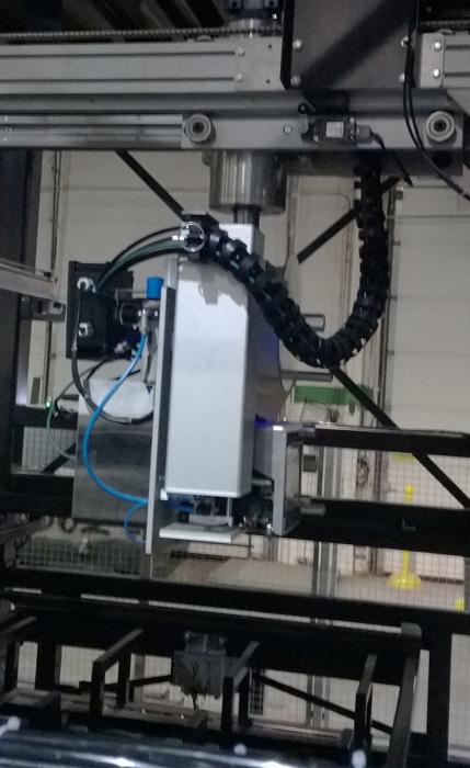
Today automated systems can apply sticky labels, which according to Bohlen hold firm yet peel off easily, to a sheet before it’s sent to the work envelope. As one job runs on the laser, the next job pulls the next sheet, and a printer unit descends to apply the labels (see Figures 5 and 6).
In a typical application, an elevator pallet brings a sheet down from a tower and presents it to the loading area, where a suction lift feeds it into the laser. With a part labeler, however, comes an intermediate step. Before the elevator pallet presents the sheet to the lifters, it moves the sheet under a labeling machine in a staging area outside the laser.
It’s basically an inkjet printer designed to print on a spool of labels. It places sticky labels on the sheet—traversing in X and Y and rotating 360 degrees—according to a location defined in the laser program, created offline. The label content and placement information for a specific part is stored for later use.
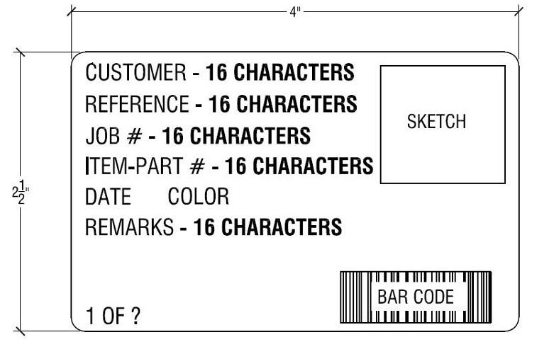
The label can be configured for the application. It could have a customer’s name, a small drawing of the part profile, a bar code (which can be scanned at downstream processes), part number, products the parts go to (“countertop unit,” “rack subassembly,” etc.), key work instructions to avoid common errors (“bend this flange down,” etc.), and various other information.
The motion for the label maker and printing requires separate programming functions, which are integrated into the nesting software. Part information can be entered manually, “but more often than not, the information is being fed from an ERP or MRP system,” said Doug Wood, sales and services director at Radan/Vero Software, Forest Lake, Minn. “The MRP system will tell us the part number, the order number, and other critical processing information. Then the program applies logic that looks at the nest and determines a good spot on the parts to place the label, so it’s not interfering with holes and things of that nature.”
Wood added that programs can be configured depending on the application and user preference. The system can automatically search and identify locations for those labels, the user may specify the location manually, or a combination of both.
An automated external part labeler may not extend cutting cycle time, because the labeler may finish a sheet before the previous job is done cutting. Still, the label printing time depends on the size and amount of information on each label.
Other part marking alternatives, be it laser etching or special punch tools, do add a little bit of cycle time. But as sources explained, it’s a matter of seconds or minutes—and that’s nothing compared to the time and money spent hunting for and recutting lost or incorrectly formed parts.


The Fabricator is North America's leading magazine for the metal forming and fabricating industry. The magazine delivers the news, technical articles, and case histories that enable fabricators to do their jobs more efficiently. The Fabricator has served the industry since 1970.
start your free subscription
Easily access valuable industry resources now with full access to the digital edition of The Fabricator.

Easily access valuable industry resources now with full access to the digital edition of The Welder.

Easily access valuable industry resources now with full access to the digital edition of The Tube and Pipe Journal.

Easily access valuable industry resources now with full access to the digital edition of The Fabricator en Español.
In this episode of The Fabricator Podcast, Caleb Chamberlain, co-founder and CEO of OSH Cut, discusses his company’s...


