


Contributing Writer
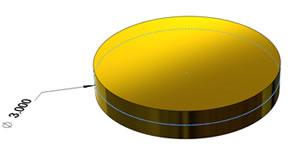
Figure 1: An example of a simple extrude based on a sketched circle is shown.
One of the core skills to have when operating a 3-D CAD system is the mastery of extrudes. With enough extrudes, almost any product can be modeled.
However, other tools in the 3-D CAD arsenal—revolves, sweeps, and lofts—can be used to improve the modeling process as well.
Figure 1 shows a boss that was created as an extrude of a sketch based on a 3-inch-diameter circle. The circle was extruded from a midplane for a distance of 0.5 in. Figure 2 is a similar part that was created using a revolve of a sketch based on a 0.5-in. by 1.5-in. dimensioned rectangle.
Which model is better? Without considering the purpose of the model, let's take a look at some statistics as shown in the following table:
The modeling time will vary from person to person. In this simple modeling challenge, I needed several mouse clicks to select a plane, select a sketch tool (circle or rectangle), click and drag to create the sketch, select a dimension tool, add the dimensions, exit the sketch, and specify the distance/direction of the extrude. The difference in modeling time—the revolve took slightly longer—was largely because of the additional dimension and the need to select an edge for the revolve. These two models are basically identical, and both are very easy to create.
The rebuild time is the amount of time it takes the computer to display the part. The software has to interpret the sketch, the dimensions, and the projected angle of the viewport; create the surfaces; and hide the appropriate surfaces. As the number of surfaces and the complexity of the sketches increase, the rebuild time will get longer. If you are modeling a part that will be used repeatedly in complex assemblies, you should pay attention to the rebuild time when it comes to deciding how to model a part.
You can see in the table that both of these simple models took virtually no time to rebuild. However, the calculation surfaces based on an arc (the extruded circle) took just a little bit longer than the calculation based on lines (the revolved rectangle). The important point to remember is that the modeling techniques that you use will have an impact on how hard the computer has to work in order to display the result.
If you have the luxury in your work schedule, I recommend that you refine your model for the CPU's benefit. For most of the projects I work on, other considerations take priority over rebuild time, but it is still a point of proficiency to produce models that make the computer happy.
Figure 3 shows two models of a pulley. Dimensionally, the models are identical. The one on the left was created with simple extrudes. I didn't want to mess with trigonometry to figure out the length of the taper, so I may have wasted a step or two to get the model completed quickly.
The model in the right panel in Figure 3 was created from a single sketch that represents the cross section of the pulley. The sketching was more complex, but only one sketch was required, compared with the six circles sketched for the extruded version.
Let's do a statistical comparison between the models shown in Figure 3. The features and rebuild time were collected using the Feature Statistics tool built into my 3-D CAD software. In this example, using a revolve proved 10 times faster, as far as the CPU is concerned.
From a modeling point of view, the extruded version required only circles in the sketches. If I had been restricted to using only the tools that I learned in the first five minutes of training with the 3-D CAD software, this would be the result. The revolved version took a little more effort in terms of sketching the cross section. I also had to use a tool (revolve) that is covered later in the training material.
An additional benefit to the revolved modeling technique is evident when it comes to revising the design. With all of the dimensional features in a single sketch, it is very easy to edit the cross section.
In this example, the revolve makes sense as a 360-degree feature. However, you can see in Figure 4 that it could be limited to 270 degrees, or any other amount of rotation, if that was needed in the model.
Limitations exist in terms of what can be modeled with revolves, of course. As shown in Figure 5, the best way to model the broached keyway is to use an extrude.
Sometimes it is important to model the part in a way that reflects the manufacturing process. If a company were making illustrations for an instruction manual (see Figure 6) on how to build a pulley on a lathe, the model probably would start out with a simple extrude to represent the billet, then a cut to produce the collar, another cut to create the V-slot for the belt, and a final cut down the middle for the shaft.
Figure 7 shows the model that was used to create the illustration shown in Figure 6. Note that this model is a combination of extrudes, extrude cuts, and cut revolves. It rebuilds in 0.05 second and has only eight features—a pretty efficient model. I created a series of configurations in the model to reveal progress in the manufacturing steps.
As always, if you'd like to get a copy of these models to play with, just let us know. These models were created in SolidWorks 2009, so if you're using a different CAD system, let us know which file format you can import.
Next month I'll take a closer look at using sweeps as a modeling technique to create 3-D solid bodies. These can be terrific for creating models of plumbing and other exotic shapes.
Gerald would love to have you send him your comments and questions. You are not alone, and the problems you face often are shared by others. Share the grief, and perhaps we will all share in the joy of finding answers. Please send your questions and comments to dand@thefabricator.com.


The Fabricator is North America's leading magazine for the metal forming and fabricating industry. The magazine delivers the news, technical articles, and case histories that enable fabricators to do their jobs more efficiently. The Fabricator has served the industry since 1970.
start your free subscription
Easily access valuable industry resources now with full access to the digital edition of The Fabricator.

Easily access valuable industry resources now with full access to the digital edition of The Welder.

Easily access valuable industry resources now with full access to the digital edition of The Tube and Pipe Journal.

Easily access valuable industry resources now with full access to the digital edition of The Fabricator en Español.
In this episode of The Fabricator Podcast, Caleb Chamberlain, co-founder and CEO of OSH Cut, discusses his company’s...


