Contributing Writer
In an automobile, the heat source is the combustion chamber inside the engine, which operates at temperatures in excess of 2,000 degrees F. In a plasma torch, the heat source is the plasma chamber inside the torch, where the temperature of the arc can exceed 20,000 degrees.
A plasma torch, like an engine, is cooled by a combination of radiation, convection, and conduction. Energy radiates from the arc in the form of intense ultraviolet rays. Heat convects away from the torch and torch parts through moving gas or air. Finally, the water-cooling system conducts heat away from the torch parts into the coolant.
So what happens when a problem with a component in the cooling system reduces conductive cooling? The system overheats rapidly.
 |
| Figure 1 This cross-section view of a plasma torch shows the internal passages for cooling water. |
Anyone who has overheated an automobile knows the inconvenience of being stranded on the side of the road with a steaming vehicle and the expense of cascading repairs that typically follows, such as new radiators, hoses, a head gasket, or even an engine block.
When a plasma system overheats, it also will cost you time and money. An overheating plasma system will wear out torch parts quickly and eventually may burn out the torch and leads. If the problem goes uncorrected, you may have to replace a motor and pump.
But you can avoid the downtime and expense of overheating. Understanding the system and its components will help you troubleshoot problems when they occur and prevent future failures through preventive maintenance.
A typical plasma arc cutting (PAC) cooling system consists of a torch, motor, pump, coolant and cooling lines, flow switch, filter, heat exchanger, and reservoir.
The Torch. Plasma torches that operate at 100 to 150 amps and higher (15 kVA) require water cooling to keep the torch and parts from overheating (see Figure 1).
The copper electrode generates the plasma arc and is closest to the heat source, so it requires direct cooling. Most high-power electrodes are hollow-milled to allow for improved cooling at the tip. A water tube extends into this milled area, closely spaced and precisely aligned to the electrode—usually 0.015 to 0.020 inch clearance per side—and provides a high flow velocity of coolant over the interior rear surface of the electrode. In this torch design, the nozzle also is cooled by water.
Common problems with torches include the following:
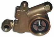 |
| Figure 2 Rotary vane pumps often are called carbonator vane pumps because the moving vanes of the pump are made of a carbon composite material. |
Clogged torch. Torches can clog up over time with particulate. Particles of melted copper from failed electrodes can plug small holes and reduce or cut off water flow.
Damaged water tube.If the water tube is bent, damaged on the end, or not threaded into the torch properly, it will reduce cooling water flow.
Leaky torch.Damaged O-rings or O-ring sealing surfaces can cause leaking of the cooling fluid. Tubes and fittings at the back of torch may weep coolant, causing low tank levels.
Pump and Motor. Typically motors and pumps in plasma systems are coupled directly. The service life of a motor usually is long—several years—unless restrictions in the system cause the motor and pump to work harder.
Rotary vane pumps are used most often in plasma systems because they're relatively simple and robust. They're often called carbonator vane pumps (see Figure 2). These pumps usually are adjustable via a bypass screw that increases or decreases the operating pressure and flow of the pump.
Common problems with pumps include:
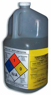 |
| Figure 3 One component of torch coolant is de-ionized water, which must be used because it is free of conductive ions that can cause problems in the system. |
Normal pump wear.Some carbon vane wear is normal, caused by friction and heat from constant use. Adjusting the pump can compensate for this condition.
Excessive pump wear.Bearings in the pumps may wear out eventually, causing excessive noise, heat, and, ultimately, pump failure. The material in the pump vanes can become worn down until the pump will no longer develop pressure. These parts usually can be replaced if the pump is sent in for a factory recondition, or the pump may need replacement.
Clogged pump filter.Most rotary vane pumps have a small screen filter. This filter may clog with particulate, causing a flow restriction.
Coolant. Torch coolant is a mixture of de-ionized water and ethylene or propylene glycol to depress the freezing point (see Figure 3).
Many shops use plain de-ionized water if there is no risk of freezing. Ethylene or propylene glycol is the same agent used in automotive cooling systems. However, never use automotive antifreeze in a plasma system. Most commercial antifreeze has material in it to clog small leaks. This makes it unsuitable for use in a plasma torch.
Common problems with coolant include the following:
Contamination.Over time, coolant can become contaminated by bits of hose, wire, or copper from failed parts, as well as dirt, rust, algae, and other contaminants. These contaminants reduce cooling efficiency and lower the flow rate. Your system may require flushing, a new filter, and new coolant.
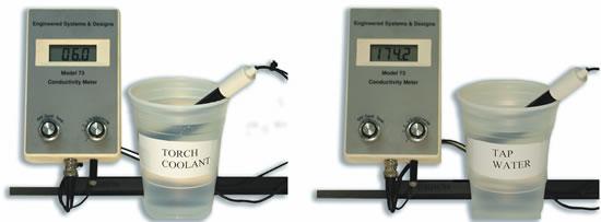 |
| Figure 4 In measuring the conductivity of coolant, you should use OEM coolant or periodically test the coolant conductivity using a special tester. The recommended level is between 0.5 and 18 micro Siemens/cm. |
High conductivity.If the coolant's conductivity is too high or if the resistivity is too low, electricity may conduct through the cooling water in the torch. This can cause hard starting of the plasma arc when the torch is striking an arc between the electrode and nozzle. Even new coolant not made to the manufacturer's specification may not meet the conductivity requirements of the system. (see Figure 4).
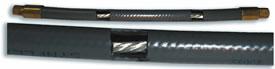 |
| Figure 5 This coolant hose cutaway view shows the power cable inside. |
Cooling Lines. Cooling lines are hoses that carry coolant to and from the plasma torch. These usually contain the main direct current (DC) power cables as well (see Figure 5). Water-cooled power cables prevent the multistranded copper or tinned copper wire from overheating. In mechanized applications, cooling lines usually are routed through flexible power track or festooned above the cutting machine.
Common problems with cooling lines include:
Leaks.Cracked, cut, or melted hoses may leak cooling fluid in areas that cannot be seen. A common spot for a leak is just above the torch inside the mounting tube.
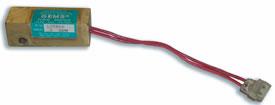 |
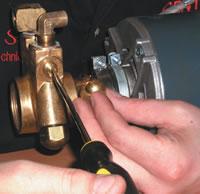
| Figure 6 Problems common to flow switches are mechanical failure and electrical failure. |
Restrictions.Flow restrictions most commonly form in the return line from the plasma torch to the recirculator. Debris accumulates in return lead restricting flow. The tinned copper power cables also can break down from constant flexing, allowing filaments of copper to clog up the ends of the hoses. Restrictions in the leads cause reduced flow and increased wear on the pump and motor.
Flow Switches.Flow switches are designed to prevent catastrophic torch and parts failure in the event of low coolant flow (see Figure 6). Brass block plunger-type devices typically are used with a microswitch that must be satisfied for the system to run.
Common problems with flow switches comprise:
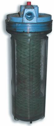 |
| Figure 7 Coolant filters should be changed every few months or whenever flow in the system is reduced. |
Mechanical failure.Coolant flow actuates a mechanical plunger. The plunger can stick in the open or closed position, causing a fault condition or no fault even in low-flow conditions. The mechanical portion sometimes can be removed and cleaned, but it's best to replace it.
Electrical failure.Electrical switch failure is less common, but it can occur if switch contacts wear out.
"Jumpered"out. It's not uncommon to find flow switches "jumpered" out of the system from previous troubleshooting. This is a dangerous practice because the flow switch is the safety feature that prevents a major torch failure caused by overheating.
Filters. Most systems use a particulate filter to remove contamination from the torch coolant (see Figure 7). These filters are similar to commercially available water-treatment filters, usually a 5-micron paper filter or de-ionizing filter.
Common problems with filters include contamination, using an incorrect filter, or using no filter.
Heat Exchangers. Heat exchangers for plasma cooling systems usually consist of a radiator and fan combination (see Figure 8). Fans direct airflow through the radiator to remove heat from the torch coolant. Some systems use a refrigerated chiller to cool the torch coolant.
Common problems with heat exchangers include:
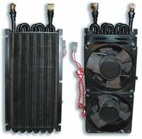 |
| Figure 8 Problems to look for with heat exchangers are fan motor burnout and reduced efficiency. |
Fan motor burnout.Check all fans periodically to make sure they are performing.
Reduced efficiency.Dirt buildup on the cooling fins reduces the cooling efficiency. Clean the radiator periodically using compressed air.
Coolant Reservoirs. The coolant reservoir is a plastic or metal tank that holds the torch coolant (see Figure 9).
Check the coolant reservoir daily and top it off as necessary to make sure the coolant supply always is adequate. If coolant levels are too low, air may be introduced into the coolant stream, which reduces cooling. If the system is interlocked, low coolant may cause intermittent or total shutdown. If the system is not interlocked, air may cause the pump to overheat and fail.
Common problems with coolant reservoirs are:
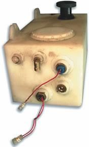 |
| Figure 9 Coolant reservoirs usually have level indicators, float switches, and temperature switches installed in the tank to prevent overheating. |
Particulate contamination.Particulate may accumulate in the bottom of the tank. Flush this out and remove it. You also may need to remove and steam-clean the tank periodically.
Inadequate coolant level.
The individual components in the plasma cooling system all are designed to ensure one thing: an adequate volumetric flow rate to the torch for cooling.
Flow typically is measured in gallons per minute (GPM) or liters per minute (LPM). Each torch has a specific flow requirement in the specifications section of the operator's manual. Typical flow rates are 1 to 1.5 GPM.
The following is a five-step approach for verifying proper coolant flow and troubleshooting flow problems. Before performing maintenance and troubleshooting on a plasma system, always read your operator's manual and understand all safety precautions.
1. Remove torch parts. When troubleshooting, begin at the torch. Remove the consumables and inspect them for signs of overheating, contamination, or damage.
2. Turn on coolant pump. You may need an assistant to keep the pump running during flow measurement and to top off the coolant level if it gets low. Coolant should flow directly out of the center of the cooling tube in the torch.
 |
| Figure 10 Adjust the pump pressure if it is too low when you're measuring the coolant supply flow to the torch. |
3. Measure coolant supply flow to torch. Use a bucket to catch coolant that is discharged from the cooling tube. Collect coolant over a time interval of 30 seconds and then shut off the pump.
Measure the volume of coolant in gallons or liters. Convert this volume to a flow rate by dividing gallons collected by the time interval (30 seconds) to attain GPM or LPM. Compare this measurement to the specified flow rate in the operator's manual. The flow in an unrestricted torch (without parts in it) should exceed the manufacturer's specification. If it doesn't, check to see if:
The pump pressure is too low. If it is, adjust the pump setting (see Figure 10).
The screen filter in the pump is restricted. Clean it if necessary (see Figure 11).
The torch or its supply line is restricted. Blow debris out with compressed air or replace if needed.
4. Reassemble the torch. Using clean new parts, reassemble the torch. Parts must be in place for a proper flow check since the electrode and water tube offer the major restriction.
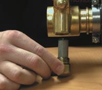 |
| Figure 11 Remove and clean the pump screen filter if it is restricted when you're measuring the coolant supply flow to the torch. |
5. Measure the coolant return flow from the torch. Measure the coolant flow rate at the return to the coolant reservoir. Disconnect the plastic hose from the coolant tank. Again, use a bucket and an assistant to collect water for a 30-second interval then shut off the pump. Convert the measurement to GPM. Compare this flow rate to the manufacturer's specification. If the GPM doesn't exceed the manufacturer's specification, check to see if:
The pump pressure is too low. If it is, adjust pump setting.
The return coolant line or torch is restricted. If so, blow the debris out with compressed air or replace it.
The radiator is plugged. Use a high-pressure washer to clean it or replace it if necessary.
The paper filter is restricted. Replace it or remove it temporarily for troubleshooting if necessary.
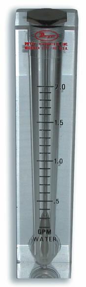 |
| Figure 12 A liquid flowmeter is an alternative to the bucket test commonly used to measure coolant flow to and from the plasma cutting torch. |
If necessary, you can check the flow on the downstream side of each suspect component until a restriction is found.
An alternative to the bucket test is to purchase an inexpensive flow meter designed for liquid flow measurement in the range of 0 to 2 GPM (see Figure 12). This device can be installed permanently in the return side of the system at the reservoir. It is a suitable visual tool for maintaining the plasma system and cheap insurance against a costly breakdown.
David Cook is the technical service director and Jason Start is a technical service representative with Centricut LLC, Two Technology Drive, West Lebanon, NH 03784, 800-752-7623, fax 800-317-0438, djcook@centricut.com, jnstart@centricut.com, www.centricut.com.
Photographs by Debra Lavoie, graphic designer for Centricut.

The Welder, formerly known as Practical Welding Today, is a showcase of the real people who make the products we use and work with every day. This magazine has served the welding community in North America well for more than 20 years.
start your free subscription
Easily access valuable industry resources now with full access to the digital edition of The Fabricator.

Easily access valuable industry resources now with full access to the digital edition of The Welder.

Easily access valuable industry resources now with full access to the digital edition of The Tube and Pipe Journal.

Easily access valuable industry resources now with full access to the digital edition of The Fabricator en Español.
In this episode of The Fabricator Podcast, Caleb Chamberlain, co-founder and CEO of OSH Cut, discusses his company’s...