


Controlling flat-rolled shape
What's the problem? What's the fix?
Fixing a coil shape problem begins with a close examination of the defect.
While metals producers have greatly improved the quality of their flat-rolled product, your customers have tightened their specifications. Quality is a moving target. What was good enough yesterday may not be good enough tomorrow. Many metal types and grades are available. There are more equipment options. The coil world has become much more complex.
The assumption is that manufacturing and process managers know which type of equipment they want or need. Or do you? What processes do you need to make sure your coil is flat? What is flat enough? Much has been written about different types of coil shape control equipment and the theories behind them. Of the options available, which should you consider, and why?
You need to determine where you are at the start, where you want to end up, and how to get there. From a generic point of view, assuming that the equipment-builders' designs have enough horsepower, structure, and range of control, you can categorize the options.
What's the Problem?
Shape. There are two different classifications of shape defect, each requiring a different resolution. Both involve length differentials in one direction or the other.
- 1. A surface-to-surface length differential appears as longbow (coil set) or crossbow (see Figure 1).
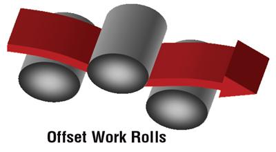
- The offset rolls of a straightener, flattener, and leveler can stretch the top and bottom surfaces to flatten the material (see Figure 2).
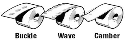
- 2. An edge-to-edge length differential appears as buckles, waves, or camber (see Figure 3).
- A leveler with adjustable roll bend can also differentially stretch the material in the rolling direction, from one edge to the other, to control waves and buckles. Adding tension to the process vastly improves the amount of elongation produced and, thus, the control of buckles, waves, and camber.
- None of these machines—straightener, flattener, or leveler—is effective for controlling crown. This is really not a shape issue; it is another problem.
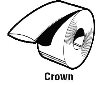
- 3. A surface-to-surface thickness differential is called profile or crown (see Figure 4). This may be either lengthwise or widthwise.
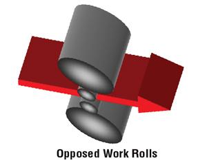
A rolling mill with opposed work rolls is required for crown control (see Figure 5). The rolling mill can also do some flatness correction. The problem is that when the cold mill reduces thickness in one area, it also elongates that area in the rolling direction. Trying to control length differential (shape) and thickness differential (profile) at the same time is asking a lot. It is optimal to let the rolling mill do what it does best—control the profile.
Once you have determined which shape problem you have, you can determine which type of equipment is effective in controlling it.
How Bad Is the Problem?
Is your shape problem minor or major? Just how bad is it? In the past stampers performed a visual inspection on a sheet or plate to determine whether it was flat enough—not a very precise measurement method. Flatness tolerances are published for most products. They refer to a wave height of so many inches in 8 or 12 feet regardless of the distance between wave and valley. For close-tolerance manufacturing projects, they are not meaningful.
What is the out-of-flat condition on incoming coil? What is the required outgoing flatness condition? It's best to apply some numbers to the shape problem. If you can describe these conditions in precise terms (in units) you can easily calculate the required reduction in strip length differential and compare it to the capabilities of equipment being considered.
Increasingly, producers and consumers are using I-units (see I-Units Versus Yield Strains sidebar) to describe the flatness of their sheet, plate, and coil. An I-unit is a measure of unflatness based on wave height and wave length. It reflects both the wave height and length that must be overcome to level the material.
A simplified formula is:
I-units = 2.467(H/L)2 (10)5
Where: H = wave height and L = wave length
The percent elongation (strain) required for leveling is directly proportional to the measured number of I-units. One percent length differential is equal to 1,000 I-units. Thus, one I-unit equals 0.01 percent length differential. The difference between the incoming shape and the desired outgoing shape can be shown as a percent length differential in the material. To achieve the desired flatness requires that much permanent elongation of the shorter parts of the product.
The formula is:
(Ii-Io)/1,000 + 1YS x 100 = Percentage of elongation required to achieve the desired flatness.
Where: Ii = Incoming I-units, Io = Outgoing I-units
and
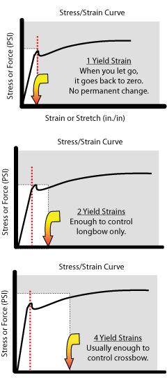
1YS = Elongation (strain) to yield point or yield strength/modulus of elasticity.
This is the material elongation setting for stretch or tension leveling systems.
The entry and exit roll gap settings for straighteners, flatteners, and levelers are more difficult to calculate, but they achieve the same end—elongation of the short parts of the metal.
So, What's the Fix?
Refer to Table 1 to determine the appropriate types of equipment for control of your shape problems. Next, using the formula above, calculate the elongation required to achieve flat material. Compare that with the degree of shape improvement possible with various types of equipment (see Table 2). Double check your goals and materials for other concerns, the degree of shape control required (see Table 3), and target I-units (see Table 4).
Shape Compensation
Most of the approaches described assume that you want your flat-rolled material to be flat, but that may not be the case. Some stamping and roll forming processes create unintended length differentials in the metal. In many cases, the fix is to do the opposite before the material enters the stamping or roll forming dies. For example, the dies might create edge wave caused by gathering in the center of the panel. The fix could be to prestretch the center with a leveler so that the part comes out of the dies evenly. This actually works.
Imagine ordering coils 16 in. wide with 1-in. waves on 18-in. centers on one side and ¾ in. high on 12-in. centers on the other side. That is tough to do—on purpose. Shape compensation can be done only with a leveler equipped with adjustable roll bend, and it must be in the line right before the dies.
Material Variations
Settings change with changes in yield strength or modulus of elasticity (see Table 5). Some design issues may arise regarding range of thickness. For instance, a machine designed for a certain thickness of steel may not necessarily flatten the same thickness of aluminum.
At elevated temperatures, both the yield strength and the modulus required decrease. Because the material cools rapidly during processing, the temperatures and physicals may vary. Optimal machine settings may also change.
Production Rates
Some of these processes can operate at higher speeds. Speed capacity may not be important on very thick plate, but it may be critical on light-gauge coil. Coil setup time may vary from operation to operation. The actual processing time is what it is. See Table 6 for comparative speed ranges.
What's the Fix Going to Cost?
What's the cost? That should be the last question you ask, not the first. Coil processors can perform leveling at competitive rates, or stampers can perform it if volumes make it cost-effective to do so. If you already have a proper feeder for your existing press, calculate the savings in inspection costs, reject parts, or tinker-with-the-die time for cost justification. Either way, the first question should be "What's the right equipment?" not "Who owns it?"
Eric Theis and Tom Hazen are partners for Consultants to the Industry, 305 Elwick St., Sewickley, PA 15143, 412-741-2111, etheis@comcast.net. The company performs consulting and training.
Notes
- See Yield Strain and Roller-type Shape Control sidebar.
- Introduce controllable edge wave or buckle.
- Percent of web tension to yield strength.
- Excluding pure stretch leveling systems.
- Stretch leveling is not effective for control of crossbow. Most designs include a separate crossbow correction section.
- Assuming a flatness goal of about 5 I-units or fewer.
- Percent of web tension to yield strength.
- Ibid.
- Typical. May be better or worse depending on incoming shape.
- Ibid.
- Percent of web tension to yield strength.
- Ibid.
- These processes can be used on most nonferrous metals if proper design allowances are made.
- Lower ratio for higher yield.
- Assumes larger rolls for heat dissipation. May not be viable with small work rolls.
- May also be expressed in metric measure.
About the Authors

Eric Theis
About the Publication

subscribe now

The Fabricator is North America's leading magazine for the metal forming and fabricating industry. The magazine delivers the news, technical articles, and case histories that enable fabricators to do their jobs more efficiently. The Fabricator has served the industry since 1970.
start your free subscription- Stay connected from anywhere

Easily access valuable industry resources now with full access to the digital edition of The Fabricator.

Easily access valuable industry resources now with full access to the digital edition of The Welder.

Easily access valuable industry resources now with full access to the digital edition of The Tube and Pipe Journal.

Easily access valuable industry resources now with full access to the digital edition of The Fabricator en Español.
- Podcasting

In this podcast episode, Brian Steel, CEO of Cadrex Manufacturing, discusses the challenges of acquiring, merging, and integrating...


