


Contributing Writer
When competing in a global economy, it pays to weld it right the first time.
Rework and scrap add significant cost to a manufacturer's balance sheet. Missed delivery dates increase customer dissatisfaction and defection. Poor weld quality may even cause a customer to carry excessive inventory. What business can thrive with reduced cash flow and ambiguous lead-times?
Assessing weld quality brings to mind the taskmaster sergeant in front of soldiers lined up for inspection. Appearance? Check. Precision? Check. Uniformity? Check, check.
As with a platoon of soldiers, passing weld inspection involves several considerations. From start to finish, gases and gas supply equipment are key factors.
For a job shop or manufacturer, maintaining weld quality begins with consistent shielding gas in the gas metal arc welding (GMAW) process. Consistently delivering the correct blend ensures proper arc characteristics and weld quality. Mixing technology, supply gas density, and gas usage patterns can affect the on-site gas blending system's ability to deliver a consistent blend.
The most common materials welded are mild steel, aluminum, and stainless. This discussion will focus on mild steel. Weld defects like undercut, lack of penetration, and porosity affect each material in similar fashion.
Two common types of gas blenders are proportional and pressure differential.
Proportional Blender. This simple, nonelectric design maintains equal pressure into the mixing chamber by using the incoming supply of one gas component to pilot both inlet gas source regulators.
When flow demand exceeds 50 square cubic feet per hour (SCFH), the pressure across the mixing valve is constant, delivering an accurate mix. However, when flow demand dips below the designed range, such as during production break periods and weekends, the mix can drift because of the droop of the inlet regulators and the inherent difference in spring-closing force acting on each seat.
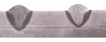
The mixture can become either lean or rich. A gas mixture rich in argon will cause the arc to lengthen, which increases the voltage from the electrode tip to the weld joint and causes the energy across the arc to fan out, increasing puddle fluidity. As the base material flows, it leaves a concave (undercut) area around the weld bead edges (see Figure 1).
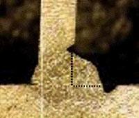
Figure 1: As the base material flows, it leaves a concave (undercut) area around the weld bead edges. (Photo courtesy of Ed Craig, weldreality.com.)
A mixture rich in argon balanced with CO2can cause a lack of penetration (see Figure 2). Its low thermal conductivity constricts the energy across the arc, elevating the driving force and subsequent penetration.
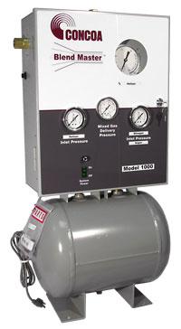
Pressure Differential Blender. The pressure differential gas mixer includes a surge tank, electric pressure switch, and electric solenoid valve (see Figure 3) to help ensure pressure drop is controlled across the mixing chamber.
The solenoid valve stops the gas flow out of the mixing chamber under low-use conditions, preventing a poor mixture from filling the surge tank and pipe line. The pressure switch maintains the surge tank pressure between 58 and 72 pounds per square inch gauge (PSIG) and activates the solenoid valve to open and close, allowing gas from the mixing chamber to fill the surge tank. The surge tank provides a buffer while the mixing chamber replenishes the consumed mixed gas.
This mixer requires an external electrical supply. Maintenance is necessary on the electrical pressure switches and solenoid valves, the result of normal wear and tear. The electrical components also can be detrimentally affected by poor input power quality.
If the gas supply system feeding the mixer is undersized, undercut and lack of penetration can result. The minimum usage threshold to convert from high-pressure cylinders to an on-site mixing system usually is 2,200 to 3,000 cubic feet per week. High-pressure cylinders are typically 48 in. to 60 in. tall and 9 in. in diameter. The typical high-pressure cylinder holds 240 cu. ft. to 340 cu. ft. of pure or premixed product in gas phase pressurized between 900 pounds per square inch (PSI) and 2,650 PSI. External vaporization is not required, but a manifold of multiple cylinders may be necessary to provide additional volume at the point of use.
An on-site gas mixing system produces a precise blend of shielding gas from two or three sources of pure gases. Blending system components include a blender as illustrated in Figure 3, a primary and secondary gas delivery system.
On-site mixers can be supplied by bulk tanks, microbulk, or liquid cylinders. Bulk tanks require an external vaporizer that converts liquid to gas. Microbulk and liquid cylinders offer both liquid and gas phase withdrawal. Problems can arise when the mixer demands higher input than the cylinders' internal gas vaporizing coils can generate.
As a result, the coils become saturated and the gas temperature falls, causing ice to form on the valves and sides of the liquid cylinder (see Figure 4). Gas density increases as its temperature plummets, causing an imbalanced mixture. The mixing chamber orifices usually are sized and calibrated to operate at between 32 and 100 degrees F. The resulting mixture becomes rich in either component, causing undercut or lack of penetration.
Gas consumption patterns in the manufacturing or job shop environment have an impact on the on-site mixing system. As demand increases, the pressure differential mixer's solenoid valve stops cycling on and off after 500 cu. ft. per hour (CFH) for mixers with less than 1,000-CFH capacity. This places a continuous demand on the supply system to maintain pressure to the mixture between 100 PSI and 125 PSI.
If one component drops out of this range, the mixture will vary. When using liquid cylinders, it is necessary to match the mixer's maximum flow capabilities with the correct number of liquid cylinders. A standard liquid cylinder can deliver gas phase up to 350 to 400 CFH for about one to two hours of continuous withdrawal. Beyond that, the cylinder's outlet pressure begins to drop to the mixer. A single cylinder would be insufficient for a typical 750- to 1,000-CFH mixer.
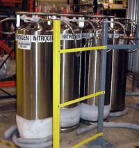
Figure 4: Overwithdrawal in a liquid cylinder causes the coils to become saturated; the gas temperature falls, and ice forms on the valves and sides of the cylinder.
A manifold is required for supplying multiple cylinders to meet the flow demand. Unfortunately, each cylinder's pressure-building circuit operates at a different pressure. The operator will never be able to set the pressure builders the same, so one cylinder dominates and closes the check valve on the other cylinder's supply hoses.
Manifolded cylinders supply only 50 percent of their maximum gas withdrawal capacity. To overcome this problem, the operator can tie the vent-use valve of each cylinder together via a common manifold. This will equalize the head pressure of each cylinder, allowing them to work together. This setup will improve withdrawal efficiency up to 80 percent.
For manufacturers and job shops alike, the maxim about profitability being won or lost in the details clearly applies. Quality products delivered on time yield the best profitability.
A properly sized on-site gas blending system and an understanding of usage patterns will improve weld quality and reduce rework and scrap.

The Fabricator is North America's leading magazine for the metal forming and fabricating industry. The magazine delivers the news, technical articles, and case histories that enable fabricators to do their jobs more efficiently. The Fabricator has served the industry since 1970.
start your free subscription
Easily access valuable industry resources now with full access to the digital edition of The Fabricator.

Easily access valuable industry resources now with full access to the digital edition of The Welder.

Easily access valuable industry resources now with full access to the digital edition of The Tube and Pipe Journal.

Easily access valuable industry resources now with full access to the digital edition of The Fabricator en Español.
In this episode of The Fabricator Podcast, Caleb Chamberlain, co-founder and CEO of OSH Cut, discusses his company’s...


