R&D manager
While only one part of a much larger system, the contact tip in both robotic and semiautomatic gas metal arc welding (GMAW) guns plays a critical role in providing sound weld quality. It can also factor measurably into the productivity and profitability of your welding operation— downtime for excessive changeover can be detrimental to throughput and the cost of labor and inventory.
A contact tip's major functions are to guide the welding wire and transfer the welding current to the wire as it passes through the bore. The goal is to have the wire feed through the contact tip smoothly, while maintaining maximum contact. To get the best results, it is important to use the right contact tip size —or inner diameter (ID) — for the application. The welding wire and welding process both influence the selection (Figure 1).
Three welding wire characteristics directly affect contact tip selection for a particular application:
Type—Contact tip manufacturers usually recommend standard- (default) sized contact tips for the corresponding wires, such as an xxx-xx-45 contact tip for 0.045-inch wire. In some cases, however, it may be preferable to either undersize or oversize the contact tip to the wire diameter.
The standard tolerances of welding wires vary according to the type. For example, American Welding Society (AWS) code 5.18 allows ± 0.001-in. tolerance for 0.045-in. solid wires, and ± 0.002-in. tolerance for 0.045-in. tubular wires. Tubular and aluminum wires, which are soft, perform best with standard or oversized contact tips that allow them to feed through with minimum feeding force and without buckling or kinking inside the feeder or welding gun.
Solid wires, conversely, are much more rigid, which means fewer feeding problems, allowing them to be paired with undersized contact tips.
Cast—The reason for over- and undersizing the contact tip relates not only to the type of the wire, but also to its cast and helix. The cast refers to the diameter of the wire loop when a length of wire has been dispensed from the package and placed on a flat surface— essentially, the wire's curvature. The typical threshold for the cast is 40 to 45 in.; if the wire cast is smaller than this, do not use an undersized contact tip.
The helix refers to how much the wire rises up from that flat surface, and it should not be greater than 1 in. at any location.
AWS sets forth requirements for wire cast and helix as quality control to ensure that available wire feeds in a manner that is conducive to good welding performance.
An approximate way to obtain the bulk number of the wire cast is by the size of the package. Wire packed in bulk packages, such as a drum or reel, can maintain a larger cast or straighter contour than wire packed in spool or coil.
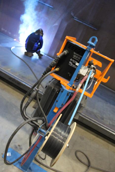
Figure 1
To get the best welding results, it is important to have the right contact tip size for the application. The welding wire and welding process both influence the selection.
"Straight wire" is a common selling point for bulk-packed wires, since it is easier to feed straight wire than curved wire. Some manufacturers also twist the wire while packing it into the drum, which results in the wire forming a sine wave instead of a loop when it is dispensed out of the package. These wires have a very large cast (100 in. or more) and can be paired with undersized contact tips.
Wire fed from a smaller spool, however, tends to have a more pronounced cast—approximately a 30-in. or smaller diameter—and typically requires a standard or larger contact tip size to provide the appropriate feeding characteristics.
Quality—The quality of the wire also affects contact tip selection. Improvements in quality control have made the outside diameter (OD) of welding wires more accurate than in years past, so they feed more smoothly. High-quality solid wire, for example, offers consistent diameter and cast, as well as a uniform copper coating on the surface; this wire can be used in conjunction with a contact tip that has a smaller ID, because there is less concern about the wire buckling or kinking. High-quality tubular wire offers the same benefits, along with smooth, secure seams that prevent the wire from opening up during feeding.
Poor-quality wire that is not manufactured to stringent standards can be prone to poor wire feeding and erratic arc. Undersized contact tips are not recommended for use with wires that have wide OD variations.
As a precaution, whenever you change to a different type or brand of wire, it is important to reassess contact tip size to make sure you achieve the desired results.
In recent years changes in the fabrication and manufacturing industries have driven changes in the welding process, as well as the size of contact tip to be used. For example, in the automotive industry where OEMs are using thinner (and stronger) materials to help reduce vehicle weight and improve fuel efficiency, manufacturers often use power sources with advanced waveforms, such as pulsed or modified short-circuit. These advanced waveforms help reduce spatter and increase welding speeds. This type of welding, typically employed in robotic welding applications, is less tolerant to deviations in the process and requires contact tips that can precisely and reliably deliver the waveform to the welding wire.
In a typical pulse welding process using 0.045-in. solid wire, the peak current can be greater than 550 amps, and the current ramping speed can be more than 1 ´ 106 amp/sec. As a result, the contact tip-to-wire interface functions as a switch at the pulse frequency, which is 150 to 200 Hz.
Contact tip life in pulse welding typically is a fraction of that in GMAW, or constant-voltage (CV) welding. Selecting a contact tip with a slightly smaller ID for the wire being used is recommended to ensure the tip/wire interface resistance is low enough that drastic arcing does not occur. For example, a 0.045-in.-diameter solid wire would match well with a contact tip with an ID of 0.049 to 0.050 in.
Manual or semiautomatic welding applications require different considerations when it comes to selecting the right contact tip size. Semiautomatic welding guns usually are much longer and have more complicated contours than robotic guns. Often there is also a greater bend in the neck, which allows the welding operator to comfortably access the weld joint. A neck with a large bending angle creates a tighter cast on the wire as it is fed through. Therefore, it is a good idea to select a contact tip with a slightly larger ID to enable smooth wire feeding. This is actually the traditional classification of contact tip sizes. Most welding gun manufacturers set their default contact tip size according to the semiautomatic application. For example, a 0.045-in. diameter solid wire would match a contact tip with an ID of 0.052 to 0.055 in.
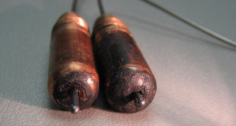
Incorrect contact tip size, whether too large or too small for the type, cast, and quality of the wire being used, can cause erratic wire feeding or poor arc performance. More specifically, contact tips with IDs that are too small can cause the wire to snag inside the bore, leading to burnback (Figure 2). It also can cause birdnesting, which is a tangle of wire in the drive rolls of the wire feeder.
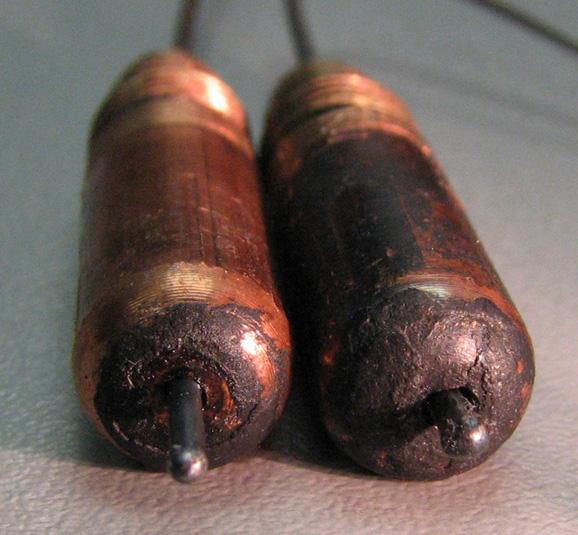
Figure 2
Burnback (wire jammed) is one of the most common failure modes of contact tips. It is significantly affected by the contact tip’s inner diameter (ID).
Conversely, contact tips with an ID that is too large for the wire diameter can allow the wire to wander as it feeds through. This wandering results in poor arc stability, heavy spatter, incomplete fusion, and misalignment of the weld in the joint. These occurrences are especially significant in aggressive pulse welding; the keyhole (Figure 3) rate (wear rate) of an oversized contact tip can be double that of an undersized contact tip.
It is important to fully understand the welding process before selecting the contact tip size for the job. Keep in mind that the third function of the contact tip is to act as the fuse of the welding system. Any problems in the powertrain of the welding loop are (and should be) shown as contact tip failure first. If the contact tip fails differently or prematurely in one cell compared to the rest of the plant, that cell likely needs fine-tuning.
It's also a good idea to assess your operation's tolerance to the risk; that is, how much it costs when a contact tip fails. In a semiautomatic application, for instance, it is likely that the welding operator can quickly identify any problems and replace a failed contact tip economically. However, the cost for unexpected contact tip failure in a robotic welding operation is much higher than that in manual welding. In this case, you need contact tips that work reliably through the period between scheduled contact tip changes, for example, one shift. It is usually true that in most robotic welding operations, the consistency of the quality provided by a contact tip is more important than how long it lasts.
Keep in mind that these are only general rules for selecting contact tip size. To determine the correct size, it is important to inspect failed contact tips in the plant. If most of the failed contact tips have wire jammed inside, the contact tip ID is too small.
If most failed contact tips are free of wires, but a rough arc and poor weld quality have been observed, it may be beneficial to select undersized contact tips.
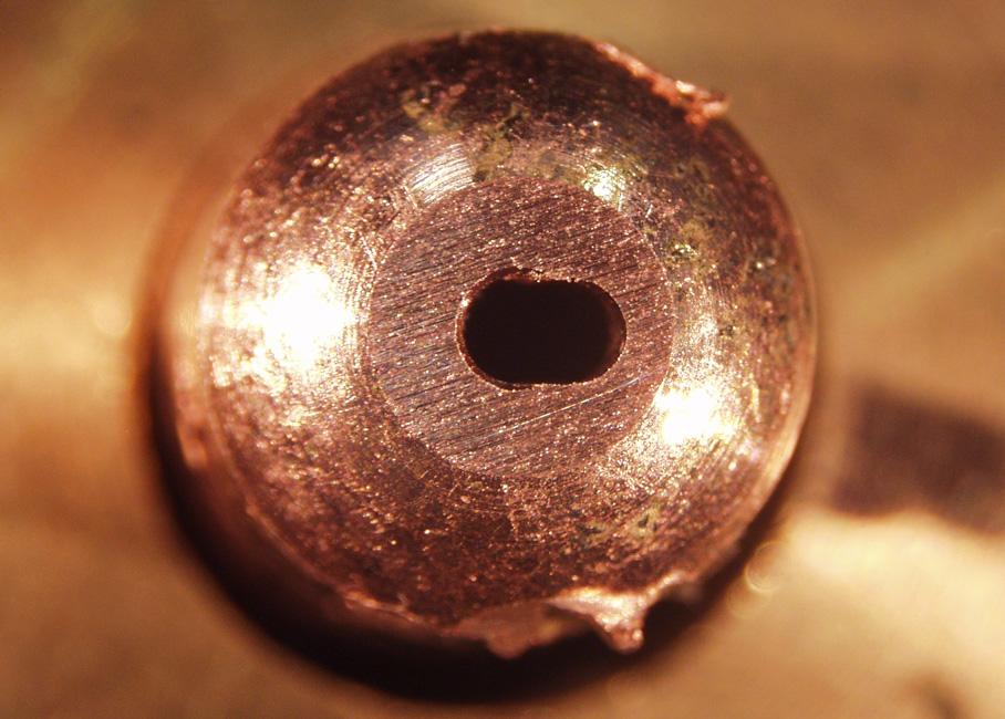
Figure 3
Excessive keyhole also is one of the most common failure modes of contact tips. It too is significantly affected by the contact tip’s inner diameter (ID).


The Welder, formerly known as Practical Welding Today, is a showcase of the real people who make the products we use and work with every day. This magazine has served the welding community in North America well for more than 20 years.
start your free subscription
Easily access valuable industry resources now with full access to the digital edition of The Fabricator.

Easily access valuable industry resources now with full access to the digital edition of The Welder.

Easily access valuable industry resources now with full access to the digital edition of The Tube and Pipe Journal.

Easily access valuable industry resources now with full access to the digital edition of The Fabricator en Español.
In this episode of The Fabricator Podcast, Caleb Chamberlain, co-founder and CEO of OSH Cut, discusses his company’s...