


President and Owner
These days the working surfaces of many cutting and machining tools are made from carbide, an extremely hard material that can withstand high temperatures and leave a good surface finish on the workpiece. Carbide’s drawback is that it is brittle; it cannot withstand vibrations or thermal shocks. Microchipping occurs when carbide is subjected to the slightest of vibrations, resulting in severe chipping until thermal degradation destroys the cutter. Tools also can shatter from thermal shock if subjected to rapid cooling, caused by interrupted coolant distribution.
On a tube or pipe mill, scarfing tools often are made from carbide. The mill and the scarfing tool almost seem to be at odds with each other; the tool needs stability in motions and temperature, and a mill’s operation is an unending source of vibrations and occasional temperature shocks. Typical vibration sources are bad mill stand bearings, improperly set mounting plates, improper tow bar alignment, weak impeder sections, weld spatter under the mandrel’s bottom roller, and loose bolts. Sometimes vibrations are caused by the cutter itself through improper geometry, improper cutter setting, or loose cutter hardware.
Eliminating or reducing vibrations and thermal shocks leads to longer cutter life, which improves the mill’s productivity by decreasing downtime.
Before looking for problems related to the mill, start by focusing on the tool itself. Its geometry, radial position, and cut depth are the three key factors in proper scarfing tool setup.
Geometry. The cutting geometry is perhaps the most important factor in achieving long run times. No single geometry is optimal for all applications. If your current cutters last less than 60 minutes, it is time to try a new cutter shape. When running coated products in light wall thicknesses, start with about 12 degrees for the relief angle and 20 degrees for the rake angle. Reduce the relief and rake angles as the wall thickness or material hardness increases.
Radial Location. The most common error made by the mill operators is related to the scarf tool’s radial location. Most operators look at the weld bead as it makes contact with the OD cutter and position the ID scarfing tool accordingly. This is not a good practice. The weld bead wanders; its position at startup isn’t necessarily the same as it is when the mill gets up to its normal running speed. It’s necessary to allow the mill to achieve a normal mill speed before attempting to set the position of the ID scarfing tool.
Cut Depth. Setting the cut depth too shallow causes more failures than setting it too deep. When the cutter is set at half or two-thirds the depth of the weld bead, the cutter is in the heart of all the impurities and hard spots. This position causes chipping and breakage. The best depth of cut is at the base of the weld with a slight undercut (0.001 to 0.003 inch). When cutting coated materials, the cutter must be set to cut precisely at the base of the weld, with an undercut maximum of 0.001 in.
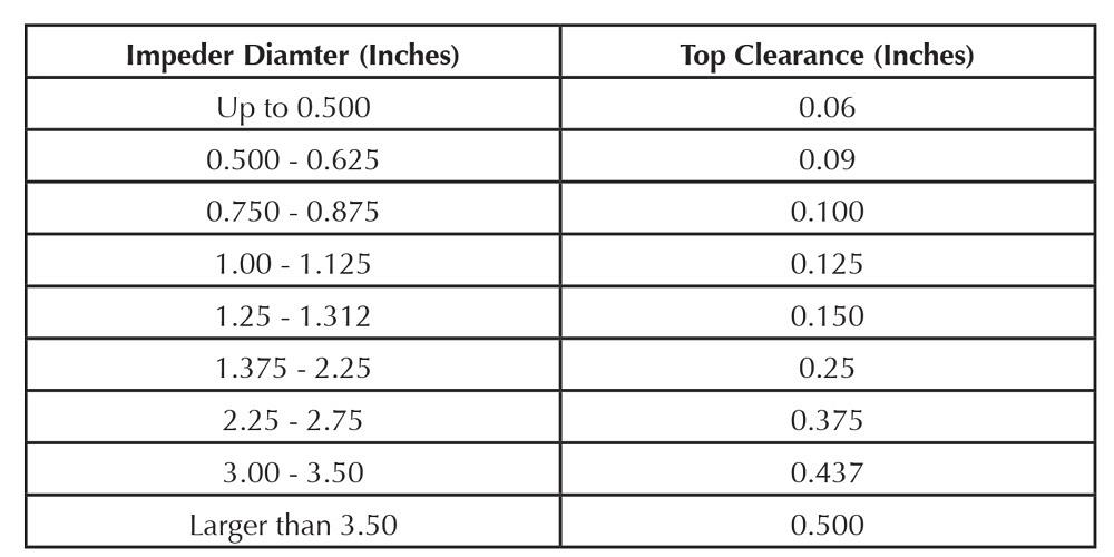
Tow Bar Position. The vertical position of the tow bar, relative to the vertical position of the impeder, is critical. Setting the mandrel too high or too low will damage the top of the impeder cover and result in an unstable cut depth (see Figure 1).
When the tow bar is set correctly, the setting meets three conditions: the tow bar is level and parallel to the tube, the top rollers and cutter contact the top of the tube, and the bottom roller contacts the tube.
Setting the tow bar too low results in a loss of welder efficiency because the ferrite mass is too low in the tube. Also, the impeder cover is likely to be damaged by debris in the bottom of the tube. Finally, to achieve a cut, the operator has to put excess pressure on the mandrel, bending the tow bar. In this situation, the cut is unsatisfactory; because the rear roller doesn’t contact the tube, the result is an inconsistent cut depth.
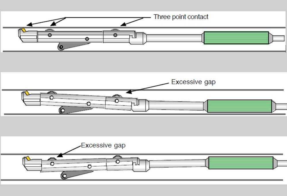
Figure 1
Setting the tow bar correctly results in three points of contact and steady, predictable scarfing. Setting it too low or too high makes proper scarfing impossible.
Setting the tow bar too high makes it impossible for the cutter to contact the weld bead; the operator has to raise the ring holder. This setting has some of the same drawbacks as setting it too low. To achieve a cut, the operator has to put excess pressure on the mandrel, bending the tow bar. In this case, the front roller doesn’t contact the tube, and the result is the same—a wavy, inconsistent cut depth.
The key to improving scarfing tooling life is to find the source of mechanical vibrations and take remedial actions. Bear in mind that some vibrations can be reduced but not eliminated.
Mechanical Shocks. Butt welds break scarfing cutters. When using a mechanical ID scarfing device, grind the butt weld smooth on both sides of the strip and run an open seam 2 feet before and after the butt weld to allow clearance in the tube at the cutter. If using a hydraulic scarfing system, drop the mandrel to the bottom of the tube when the butt weld passes over the scarfing system.
Mill starts normally cause a large cold-weld deposit that is likely to chip the cutter. When using a mechanical mandrel scarfing device, it is best to jog the open seam over the cutter, start the mill, and gradually bring up the weld power. This eliminates the large power surge that produces the large bead at the start of the weld. Again, when using a hydraulic system, drop the mandrel to the bottom of the tube when the butt weld passes over the scarfing system.
Thermal Shocks. Coolant pointed directly at the cutting point yields the best cutter wear and performance. The coolant flow must be steady—never interrupted. Stopping the coolant flow, even briefly, allows heat to build up quickly; restarting the coolant flow results in a thermal shock. This is akin to dropping a piece of superheated glass into freezing water.
The carbide cutter should be cool enough to touch as soon as the mill is stopped and the tube is opened. If the cutter is too hot to touch, the system does not deliver an ample supply of coolant. Supplying 3 to 5 gallons per minute (GPM) of focused coolant to the cutter is a good starting point. Excess coolant pressure and an extreme delivery angle (45 to 90 degrees to the weld bead) will smear and chill the weld bead, causing a sporadic weld. Conversely, a properly designed coolant flow can increase the mill speeds by 50 percent.
The impeder requires a specific amount of coolant volume. If the impeder section is burning up frequently, check the coolant delivery system. Small impeders must be supplied with coolant at 60 to 100 pounds per square inch (PSI) and sufficient flow to prevent the ferrite from reaching its Curie temperature (see Figure 2). Many tube mill coolant systems deliver 40 PSI, resulting in overheated impeders. If necessary, add a booster pump to increase the pressure.
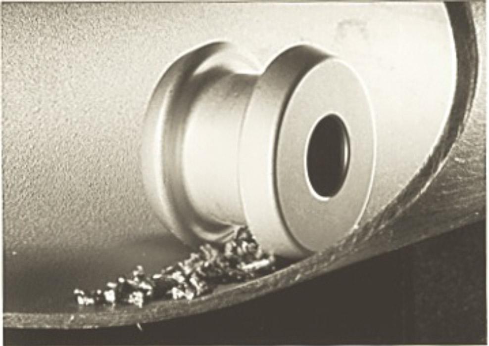
A filter placed in the coolant circuit is necessary to prevent debris from blocking the delivery and exit holes in the impeder section. The exit holes can be as small as 0.075 in. A blockage can result in the tow bar being burnt in half, breaking loose, and heading downstream towards the cutoff. The coolant filter also removes metal particles. If these metal particles are not removed, they will gather in the center of the impeder, drawn by the magnetic field produced by the induction coil. These metal particles are a common cause of impeder blockage and breakage.
Burn holes in the center of the impeder cover indicate insufficient coolant. Burn holes at the end of the cover often are caused by weld spatter buildup or abrasion.
Attempting to make several adjustments to the mill simultaneously—weld power, fin passes, seam guide, OD scarf location and depth, and ID scarfing location and height—will result in much more time wasted than saved and increase the likelihood of chipping or breaking the ID scarfing tool.
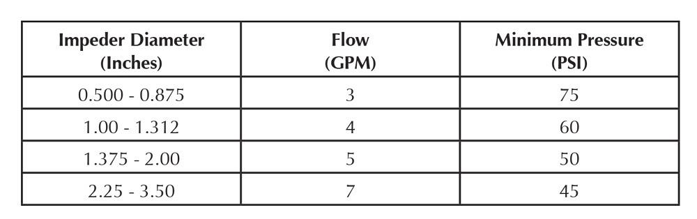
Figure 2
Keeping an impeder from overheating is a matter of proper coolant flow rate and pressure.
The best method is to set up the mill, and make any final adjustments, while running any products that don’t require scarfing, then switch to products of the same size that require scarfing. Fine-tuning the mill in this way reduces the chances for scarfing tool breakage. If all your products require scarfing, run a few test pieces and tune the mill before using the ID scarf system.
Many of the critical settings that affect the scarfing process are related to the weld box. Fortunately the conditions that produce the best weld quality also are optimal for ID scarfing.
Passline Height. The passline height must be consistent for the entire length of the scarfing system. If the passline through the weld box is lower or higher than the fin passes, the results are similar to setting the tow bar too high or too low (see Figure 1).
In some cases, setting the weld box passline slightly higher (0.010 in. on a 2-in.-dia. tube made from 16-gauge material) does not cause problems and may help. However, running with the height substantially higher increases the ID weld bead size and forms an arc that prevents the top rollers and cutter from achieving three points of contact. Setting it too low causes buckling in the tube, resulting in poor weld quality.
Upper Weld Rolls. The weld box settings must allow the strip edges to meet. They should be parallel; this allows a uniform inside weld bead and offers the best electrical welding efficiency. Another acceptable alignment is contact at the OD and a slight gap at the ID. This reduces the size of the interior weld bead.
If the strip edges are formed incorrectly before the V closes in the weld box, the mill operator must set the weld box to run an oval or peaked condition to force the strip edges to meet. A tall, peaked condition makes it difficult for the ID cutter to reach the base of the weld bead; a wide oval normally results in undercut (see Figure 3).
Profile Shape. Depending on the tube’s size, a slightly peaked condition might be necessary to achieve the best ID match with the least amount of parent metal removed. On the other hand, specifications for coated materials usually stipulate that absolutely no parent material is to be removed, so an oval or round shape is the best. Be aware that if the oval is too far from round, the edges of the cutter will contact the tube wall, preventing the cutting edge from contacting the weld bead.
Changing the burr from up to down or vice versa also affects the profile shape and weld bead size.
Impeder Settings. The most critical setting concerning the impeder and the weld box is the positioning of the ferrite in relationship to the centerline of the weld rolls. Ideally the tow bar system allows adjustments to the ferrite’s location on two axes: horizontal (forward and backward, parallel to the tube) and vertical, 1 in. upstream to 0.125 in. beyond the weld rolls (see Figure 4).
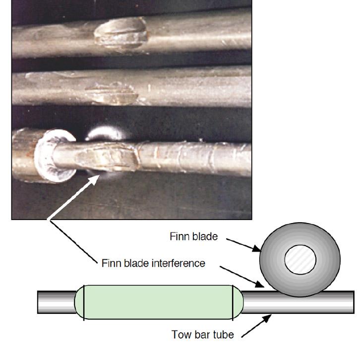
Fin Blades. Setting the fin blades too deep causes interference with the tow bar. Making the fin blades longer than normal to prevent material from rolling under is a quick fix, and a poor one, for an improper mill setup. When regrinding roll sets, be sure the fin blades’ major diameters are ground to the proper size (see Figure 5). Interference between the fin blades and the tow bar will cause a rupture in the impeder coolant circuit in just a matter of hours. A coolant circuit rupture will cause an immediate impeder failure.
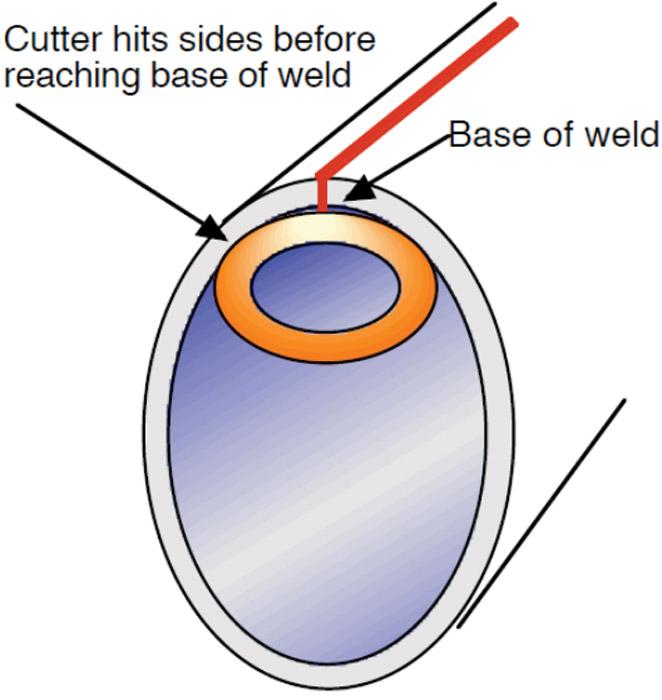
Figure 3
If the contour of the ID scarfing tool doesn’t match the coutour of the tube, the result is undercut.
Use a marker to ink the major diameter of the fin blades and later check to see if the ink remains. If it rubs off, interference with the tow bar is the likely culprit. Use the vertical adjustment at the mounting plate to lower the tow bar. If this does not eliminate the interference, the fin blades are probably too long or the tow bar is too big in diameter. Be aware that a smaller-diameter two bar will not provide the same amount of rigidity required for productive ID scarfing.
Cutter failures often occur when an inconsistent weld bead is present. A varying weld bead subjects the ID cutter to uneven cutting force loads, causing vibrations and breakage.
Weld bead inconsistencies stem from many sources. One source is excessive weld power. Too much weld power can cause molten metal to hang from the weld bead, causing the cutter to clog and break.
Another source is inconsistent weld power at the apex. These problems don’t stem from the weld power generated by the welding power supply, but conditions that change the amount of heat delivered to the apex.
Furthermore, oscillation can be problematic. Oscillation causes the weld bead shape to vary, and it can cause pre-arcing to occur. A high-frequency arc between the strip edges, pre-arc can lead to pinholes and hard spots. Pre-arc also occurs when coolant sprays into the weld zone.
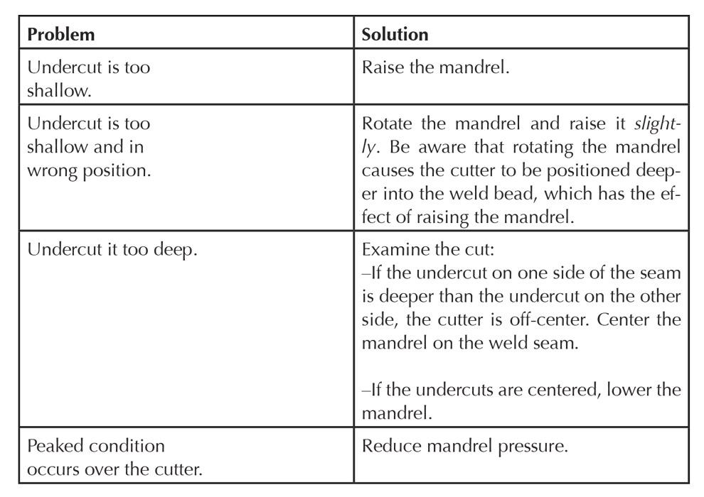
After doing everything you can to set up the ID scarfing blade, optimize the cooling system, and reduce or eliminate mill vibrations and weld inconsistencies, you’ll likely find that you have optimized most of the mill settings and thereby increased the mill’s speed and reduced its downtime. One factor remains: scarfing tool cut quality. Refer to Figure 6 to finalize the cutter settings.


The Tube and Pipe Journal became the first magazine dedicated to serving the metal tube and pipe industry in 1990. Today, it remains the only North American publication devoted to this industry, and it has become the most trusted source of information for tube and pipe professionals.
start your free subscription
Easily access valuable industry resources now with full access to the digital edition of The Fabricator.

Easily access valuable industry resources now with full access to the digital edition of The Welder.

Easily access valuable industry resources now with full access to the digital edition of The Tube and Pipe Journal.

Easily access valuable industry resources now with full access to the digital edition of The Fabricator en Español.
In this episode of The Fabricator Podcast, Caleb Chamberlain, co-founder and CEO of OSH Cut, discusses his company’s...


