


Vice President
 |
This article covers the application of single-cut and dimple-free cutoff shear technologies as they are applied to contemporary high-speed tube mills.
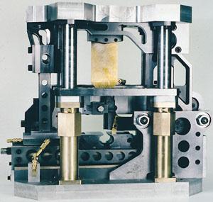
A single-cut die set is a unit composed of an upper shoe and a lower shoe in which a single severing blade and tube supporting jaws are located.
A dimple-free die set is a unit composed of an upper shoe and a lower shoe in which a horizontal scarfing blade, vertical severing blade, and tube supporting jaws are located.
As the ram of a cutoff mainframe operates, the upper shoe of the die set closes into the lower shoe with the following sequence of events. In a single-cut die set, the jaws clamp around the tube, the severing blade passes through the tube, and the die set opens again to be ready for the next cut.
In a dimple-free die set, the jaws clamp around the tube, and then the horizontal scarfing blade nicks the tube, thinning the tube wall at the point where the vertical severing blade enters the tube. The vertical severing blade then passes through the tube, and the die set opens for the next cut.
A tube cut on a single-cut die incurs distortion at the point where the severing blade enters the tube. This distortion is confined to a very small area, with the tube diameter size unchanged in the balance of the tube end.
The dimple-free cut tube is free of this distortion. The tube diameter size is not changed.
All shear-type tube cutoffs require a clearance between the blades and the jaws that typically amounts to about 10 percent of the wall thickness of the tube being cut. This necessary clearance results in a small burr that projects a few thousandths of an inch perpendicular to the tube axis. No burr-free tubes are delivered by shear-type cutoffs.
Today's tube mill cutoff systems employ both single-cut and dimple-free die sets, depending on the requirements of the application.A cutoff system consists of the die set, belt or rack and pinion accelerator, cutoff mainframe, and controls. A variety of features are available on cutoff systems:
Single-cut and dimple-free systems each possess unique capabilities.
Single-Cut. Single-cut systems tend to be quite simple in terms of components required to achieve a given specification. This simplicity leads to fewer occurrences of downtime, and the intervals of downtime are shortened. Additionally, it helps reduce maintenance costs.
Single-cut die sets are very light. These light die sets contribute to low accelerated mass, making single-cut systems suitable for very high-speed, high-cut-per-minute applications.
Single-cut die sets require shorter strokes than do their dimple-free counterparts because they do not involve a horizontal scarfing blade and its supporting components. The short stroke reduces cut time for more cuts per minute. Further, the short stroke gives the slowest possible blade speed, which helps increase tooling life.
Finally, fewer and less-complicated parts can be purchased for a much lower capital cost.
Typical applications for single-cut technology include conduit, fence, and automotive hydroformed tubulars, to name a few. Single-cut technology suits these applications because the dimpled end is easily processed in the required finishing operations, and long uninterrupted runs of high-quality product are essential.
Dimple-Free. Dimple-free systems are necessarily more complex than single-cut systems. Preventive maintenance measures are required to help manage maintenance and downtime costs.
The dimple-free die sets employed in these systems are typically three times the weight (or more) of the single-cut die set of a given capacity. As such, significantly more power is needed to achieve a given speed and cut-per-minute capacity.
Setup and changeover activities can be time-consuming. Quick-change tooling and off-line setup procedure help reduce tube mill downtime. The longer stroke required for these die sets means higher blade speeds, which contribute to increased blade and die jaw wear. However, this problem can be overcome in several ways:
Given all these facts, a dimple-free system is more expensive than a single-cut system. However, the higher cost for this technology can be justified in furniture, home appliance, and recreational tubing applications for which round tubing cut to length at the tube mill in shippable, dimple-free lengths is required.
The following case studies illustrate appropriate applications for each cutoff technology.
| Case Study 1 | Case Study 2 | |
|---|---|---|
| Material | Mild Steel | Low-carbon Steel |
| Dia. (In.) | 1.000 – 3.000 | 0.500 – 2.500 in. |
| Wall Thickness (In.) | 0.030 – 0.125 | 0.025 – 0.135 |
| Lengths (Ft.) | 1 – 20 | 12 – 20 |
| Line Speed (FPM) | 50 – 500 | 50 – 500 |
Case Study 1. This tube producer makes a comprehensive range of automotive exhaust products for the replacement market. About 70 percent of its tube production is for in-house production lines making exhaust pipes, tail pipes, mufflers, and catalytic converters. The remaining 30 percent is shipped in stock lengths to retail outlets. Production is Just-In-Time (JIT) to keep inventory costs low.
This producer has managed tube mill production very carefully and has limited tube mill capacity. However, tube mill size changes occur several times per week. The processing lines serviced by the tube mill require distortion-free tubes, as no provision is made to resize the tubing.
This tube producer chose a dimple-free system. The system was equipped with quick-change tooling to meet the frequent size change requirements.
The cutoff provided high-capacity batch/length functions to simplify JIT scheduling. At more than 100 cuts per minute for 1-foot lengths, yield (considering JIT length requirements) was better than expected. The steady supply of dimple-free tubing to the retailers and processing lines helped improved uptime.
Case Study 2. This producer of precision mechanical tube supplies 100 percent of its production to the automotive industry. Forty percent of the tube is processed into tube hydroforming lines, and the percentage is climbing. Fifty percent of the production is cut away from the mill, with a variety of flaring and grooving operations at the finishing floor. The balance of production is cut to mill lengths.
This producer needs to make top-quality tubing in all respects, considering the severe operations to the tubing. Tube size and weld quality must meet less than 5 parts per million (PPM) quality failure rates. This producer's best approach is to run the tube mill with the fewest stoppages possible to maintain consistent top quality.
The equipment of choice in this case is the single-cut system. This system's simplicity offers the required prolonged running times that are essential to this application. The tube end distortion produced by the single-cut die set is no problem to the finishing floor operations.

The Tube and Pipe Journal became the first magazine dedicated to serving the metal tube and pipe industry in 1990. Today, it remains the only North American publication devoted to this industry, and it has become the most trusted source of information for tube and pipe professionals.
start your free subscription
Easily access valuable industry resources now with full access to the digital edition of The Fabricator.

Easily access valuable industry resources now with full access to the digital edition of The Welder.

Easily access valuable industry resources now with full access to the digital edition of The Tube and Pipe Journal.

Easily access valuable industry resources now with full access to the digital edition of The Fabricator en Español.
In this episode of The Fabricator Podcast, Caleb Chamberlain, co-founder and CEO of OSH Cut, discusses his company’s...


