


Regional Sales Manager
 |
Reducing the amount of variation, or achieving more wall thickness consistency, can be the difference between meeting a customer's requirements or not. It also helps to reduce or even may eliminate the customer's need for subsequent processes such as machining.
Seamless tube typically is manufactured on a two-roll piercer mill. In some cases this step alone is sufficient to produce tube that satisfies the customer's requirements. However, if wall thickness consistency needs further improvement after piercing, a tube producer can use additional equipment and process steps. Two such types of equipment are a cross-rolling elongator mill (commonly known by its trade name, such as an Assel or a Diescher mill), and a cold draw bench.
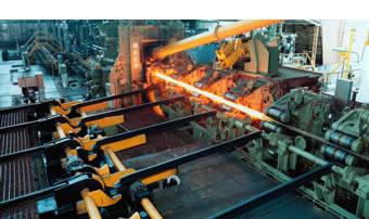
Seamless tube manufacturing usually starts with hot cross-rolling in a piercer mill. Piercing is the first process step to make tube with a high-quality wall. This step usually is followed by one or more elongation processes that can improve wall quality while also increasing tube length. After the tube leaves the seamless mill and cools, it can be finished on a cold draw bench as the third step to improve wall tolerances.
Piercer Mill. Most attention about seamless wall quality is directed at the piercer mill. This attention is justified because the piercer mill has the largest effect on wall variation. Tubing produced by a piercer mill can be optimized to 7 to 10 percent wall variation.
Although a pierced shell may have less than 10 percent wall variation, this amount of variation is for a relatively thick wall section. For example, achieving ±10 percent wall tolerance produces a tube with a wall range thickness of 13.5 mm (0.531 in.) to 16.5 mm (0.650 in.) or more when ordered at 15 mm (0.590 in.). Further processing by an elongator mill may be required for more stringent customer requirements.
 |
| Figure 1 The cross-rolling process uses three work rolls to reduce the tube's OD and wall thickness. Drawing courtesy of Copperweld, Shelby, Ohio. |
Elongator Mill. Five main types of elongator mills are used in the tube producing industry: the mandrel pipe mill, the push bench, the plug mill, the stretch reducing mill, and the cross-rolling elongator mill. Fifty years of industrywide use have shown that, of these elongator mills, the cross-rolling elongator provides the most significant improvement in wall tolerance of tube produced on a piercer mill. A cross-rolling elongator mill uses work rolls on the OD and a mandrel on the ID (see Figure 1).
Cold Draw Bench. Drawing on a bench is a cold finishing method that improves seamless tube wall dimension. In the draw bench process, first the tube is loosely threaded onto a mandrel attached to a rod. Then a plier assembly grips the tube and pulls it through a stationary carbide or tool steel die. The result is a customized tube with very good dimensional control. Typical OD tolerance is ±0.1 mm (±0.004 in.), which is roughly one-tenth the tolerance of a typical hot-finished seamless tube.
Additional benefits from the drawing process include enhanced surface finish, the ability to provide ID tolerances, and improved mechanical properties. Tubes produced with this process require minimal or additional processing and are considered value-added products.
For cross-rolling elongation, two main requirements relate to the as-pierced shell. These are filling the hump height section to 80 to 90 percent of its design and maximizing inlet side grip. Both requirements are related to the roll pass design in the Assel mill.
 |
| Figure 2 The roll hump is located near the middle of the work roll. It is important to match the tube section coming into the mill with the design features of the work rolls. Drawing courtesy of Copperweld, Shelby, Ohio. |
Filling the Hump. Hump is a general term for the region near the middle of the work roll that contains a raised profile (see Figure 2). Filling the hump is a matter of measuring the as-pierced wall and then comparing it to the known hump dimension from the print. The piercer mill is then adjusted to get the proper value. For example, if the hump design is 8 mm (0.315 in.), the as-pierced shell should measure 7 mm (0.276 in.) more than the customer size (because 7 is 90 percent of 8).
This relationship is important in thin-wall tube production because the wall tolerance for mechanical tubing is percentage-based (per ASTM standard A519). Tolerances for thinner-wall tubing are harder to achieve because, for instance, 5 percent of 5 mm (0.197 in.) is a much tighter dimension than 5 percent of 10 mm (0.394 in.). Tube producers must understand that if the mill capability is 1 mm (0.040 in.) of wall variation, this could represent half the commercial tolerance for medium-wall sections (Cp value of 2.0) and out-of-tolerance variation for thin-wall sections (Cp of less than 1.0).
The shell from the piercer mill needs to be reduced in wall thickness to ensure proper hump height filling. For extremely thin-wall tubing, manufacturers may find that quality improvement in the cross-rolling mill may be difficult if not impossible to achieve because the pierced shell has too much variation. For some tube sizes, the wall variation as a percentage may be increased rather than decreased in the piercer mill. The percentage of variation is determined by careful calculation. Although the total dimensional variation decreases the numerator, the denominator decreases at a greater rate because tube from the cross-rolling elongator mill has 50 to 75 percent less wall thickness than the tube from the piercer mill.
Cross-rolling Grip. The second requirement is to maintain the best grip in the cross-rolling process. Grip is defined as the number of tube spirals before the hump centerline in the cross-rolling elongator mill roll pass design—in simple terms, the pierced shell should contact the roll face early in the process so tube feed is established before it encounters the work zone in the hump section. The work done in the hump section requires an extreme amount of energy, up to several thousand horsepower. The work force is applied in a very short section, usually 15 to 25 mm (less than 1 in.) wide. If the tube is not gripped properly, it will spin rather than feed, or it may feed irregularly through the work zone, creating variation.
In most cases the best condition for the pierced shell is achieved by producing the maximum outside diameter that will properly fit into the cross-rolling elongator mill roll face. Usually this relationship is resolved by adjusting the piercer mill setup to produce the correct tube dimension. But in some cases it may be necessary to increase or decrease slightly the divergent angle of the elongator mill to ensure that the shell will fit and grip properly.
Experiments conducted on the wall quality of tubes taken directly from an elongator mill were used to determine whether the tubes had better wall quality than tubes further processed by a sizing mill or a stretch reducing mill. It was determined that in the sizing reduction process, longitudinal and compressive forces act on the wall and can increase wall variation. Tubes taken directly from a cross-rolling elongator mill have superior wall thickness consistency and better surface quality because they are not exposed to rolling conditions in the sizing mill. Tubes that have been through a sizing mill, however, can have wall variation reduced by cold drawing on a draw bench.
Success in processing cold-drawn seamless tube depends on maintaining high wall quality from the seamless hot mill and properly selecting the cold draw bench tools (mandrel and die sets).
Three main points that concern drawing pierced tube are:
 |
| Figure 3 Three main cold-drawing die profiles are radius, straight, and straight/radius blend, or combination. |
Cold drawing can be optimized by selecting the most appropriate die profile (see Figure 3). No single design works best for all seamless tubes because the design depends on many factors, such as wall thickness, steel grade, pass reduction requirements, and draw bench limitations.
Three die profiles are:
For each production order drawn, a statistical control chart or Student t-test method can be completed and used to optimize the die profile and die dimension as a permanent record.
For most seamless tubes, a radius die produces the best wall quality. Because the radius die has a more gradual inlet profile and smooth blend into the bearing section, the tube draw is more consistent and results in higher-quality dimensions. But there is a drawback to this type of die: Because of the gradual inlet profile, only a small OD reduction can be made on the tube. The seamless tube must be customized to use this sort of die, adding changeover expense.
Achieving consistency requires analyzing the process backward, from finish to start. The customer-specified wall thickness of the finished product provides final dimensions for tube processed by the draw bench, which guides die and mandrel selection. This selection determines the proper size tubing from the seamless mill, which determines the proper setup and operating parameters.
Wynn H. Kearns is the hot mill superintendent of Copperweld Shelby Division, 132 W. Main St., Shelby, OH 44875, 419-342-1200, fax 419-342-1437, wkearns@copperweld.com, www.copperweld.com.

The Tube and Pipe Journal became the first magazine dedicated to serving the metal tube and pipe industry in 1990. Today, it remains the only North American publication devoted to this industry, and it has become the most trusted source of information for tube and pipe professionals.
start your free subscription
Easily access valuable industry resources now with full access to the digital edition of The Fabricator.

Easily access valuable industry resources now with full access to the digital edition of The Welder.

Easily access valuable industry resources now with full access to the digital edition of The Tube and Pipe Journal.

Easily access valuable industry resources now with full access to the digital edition of The Fabricator en Español.
In this episode of The Fabricator Podcast, Caleb Chamberlain, co-founder and CEO of OSH Cut, discusses his company’s...


