


Senior Editor
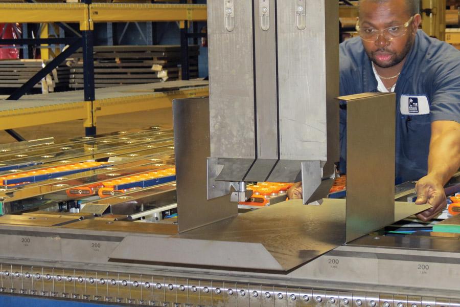
Figure 1
Atlanta’s Tie Down Engineering recently invested in a bidirectional folder with tall tooling that allows for flanges up to 19.5 in. high. Mechanically lifted corner clamping beam tools have wings that extend to the end of the bend and allow the tools to hold material underneath previously formed return flanges.
A decade ago most spending in precision metal fabrication—outside welding and consumables—occurred in the cutting department as the industry transitioned from low-powered CO2 lasers to high-powered CO2 and, finally, to solid-state technology. For the right application, a fiber laser today can run circles around a high-powered CO2 laser purchased a decade ago.
Each November at the FABTECH® tradeshow, the Fabricators & Manufacturers Association International publishes its “Capital Spending Forecast,” and for the past two years the survey has tracked a noticeable shift in spending. Collectively, shops are spending more on bending than they are on laser cutting. Driving a lot of this increase is the industry’s push toward high-end press brake technology, including offline programming software, intuitive controls, angle measurement and correction, and automated tool changing (ATC). These days, a single press brake can be a major investment.
But there’s another reason: Spending on press brake alternatives has increased too. According to FMA, purchases of other sheet metal bending equipment, including panel bending and folding, jumped by a whopping 70 percent between 2012 and 2014, to a projected amount of $134 million. The 2016 forecast number is a little lower, at $104 million, but that’s still a historically high level.
The increase really isn’t a surprise, considering the unprecedented levels of throughput coming from the cutting department. Lasers cut more parts in less time and send that work to forming—and for many, this creates a bending bottleneck they need to free.
Luckily, fabricators have options. They can upgrade to a brake with an advanced control, offline programming, and angle correction, shortening cumbersome changeovers. They also can invest in press brakes with ATC, which shortens those changeovers even more.
Still, no matter how short changeovers are, bending operators still run into problems when it comes to certain part sizes and bend geometries. Big parts are still a pain to lift. Two operators may spend half the day lifting large workpieces high into the air to bend a shallow edge flange. Robotized bending is an option, depending on the mix of parts and part volumes, but it’s not the only option.
Two alternatives to the press brake, panel bending and folding, are opening up opportunities for shops, but they also give operation managers more options to weigh and more questions to ask. Does it make sense to send a part to a panel bender or folder, even though those parts need to be sent to a press brake for a few remaining bends? Does it make sense to send parts to a folding machine in another area, or should the work stay in one area to simplify routing, even though the bending process itself isn’t quite as efficient?
According to several managers who work in bending operations with various forming technologies, the answers to all these questions depend, as they so often do, on the application.
In a press brake, force from the punch pushes sheet metal into the V-die opening to make a radius. In air forming, the process has three points of contact: the punch tip on the top surface of the sheet metal and the leading radii of the two die shoulders underneath. Different materials may require different tools, depending on the tensile strength, thickness, and required radius and angle. Modern controls, simulation, angle correction, and ATC all make changeovers less arduous, but the technology still requires changing over tools with different die openings and punch-tip radii.
In panel bending, blank holder tools clamp the sheet in place so that the material protrudes on the other side. Next, bending blades from above and below the workpiece fold the metal. For most operations, the motion of the bending blade, not the shape of the tools, determines the final bend angle and radius. The segmented blank holder tools automatically change out to match the required bend lengths.
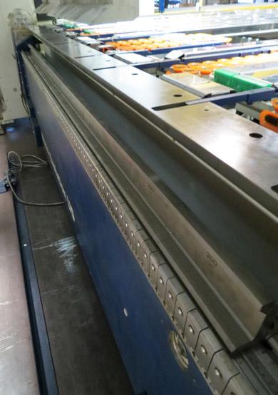
Figure 2
The folding beam changes its pivot point when changing from a positive to a negative bend, allowing the bending blade to contact the material in the right place.
Panel bending limitations include flange height and material thickness, which depend on the machine and the depth of its throat, or the area behind the blank holder tool. A deep throat can form a deep flange.
Like a panel bender, a folder clamps the workpiece with tooling; on a folding machine they’re referred to as clamping beam tools. But unlike a panel bender, a folder uses a swinging beam with a blade tool that contacts the sheet metal to make the bend. The height of the clamping beam tools generally determines the height limit for a perpendicular flange (see Figure 1).
Historically, folding beams have swung upward only; to make both positive and negative bends, an operator needed to flip the workpiece. In recent years, though, bidirectional folding systems have become more popular. In these machines, the beam pivot point changes based on the width of the bending blade tool on the beam (see Figure 2).
Say the beam blade is 0.6 inch wide. For the first upward bend, the top edge of the blade contacts the sheet to make the bend. To bend downward, the blade’s bottom edge must fold the material surface. This requires the beam’s pivot point to move 0.6 in.
The beam’s position determines the angle, and segmented clamping beam tools are arranged to handle different bend lengths. In recent years, folding systems with automatic clamping beam tool changeover have hit the market. In these machines, robotic manipulators change and rearrange clamping beam tools for the job at hand.
A machine may not have to change clamping beam tools often; one setup may be able to handle a wide variety of bends of different geometries, material types, and thicknesses. But if a series of jobs have different bend lengths and situations in which previously formed flanges would collide with clamping beam tools, ATC can help shorten the setup time between jobs (see Figure 3).
Over the past six years the fabrication department at A.J. Antunes & Co., a food preparation equipment-maker in Carol Stream, Ill., has undergone five big changes. First came lean manufacturing, 5S, and better tool organization. Second came a Salvagnini panel bender, which reduced the bending cycle times and eliminated lengthy setups for many jobs (see Figure 4). Third came offline press brake programming. Fourth came a new Amada fiber laser, which increased throughput and available cutting capacity—and increased demand on downstream bending. Fifth, and most recently, came a press brake with ATC.
“Bending has always been our bottleneck,” said Jorge Montalvo, manager, fabrication. “We started with 5S and lean. The setups went from an hour to 45 minutes. Then we saw the Salvagnini panel bender, and we thought it was great, because we do a lot of box bending. Once we got that, everything took off.”
Montalvo added that the panel bender doesn’t work for every part. A part needs a flat surface to be positioned for a bend, and flanges can be only so high. But having the machine does allow the company to produce extremely complex bends in fewer setups.
To increase its panel bending flexibility, the fabrication department now has a press brake directly adjacent to the panel bender. “Say a complex part requires five different setups on the press brake,” Montalvo said. “Now the panel bender does four of those five setups, and the operator turns around and finishes the part on the press brake.” He added that using another machine does increase handling time, but that slight increase in handling time is more than offset by all the setup time that the panel bender has eliminated.
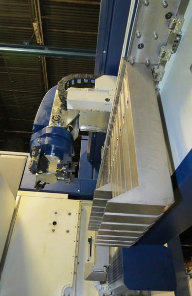
Figure 3
In this ATC setup on a folding machine, robotic manipulators move and rearrange clamping beam tools.
Montalvo’s team followed a similar line of thinking when they re-evaluated production methods for various small brackets, which took a lot of time for the operator to form at the press brake. The company’s panel bender requires parts to be a certain width.
So why not microtab these parts together on the company’s TRUMPF laser/punch combination machine? This way, the panel bender operator retrieves a large blank of small parts microtabbed together and inserts them in the panel bender, which then forms all the parts at once in a few seconds (see Figure 5). After this, the operator snaps the components apart and sends them on to be deburred.
Montalvo said that this decision didn’t happen without debate. After all, this strategy did add an extra deburring step. The company even tried using a special tool in the punch press that would allow the parts to be snapped apart cleanly, no deburring required. But as it turned out, the punch tool didn’t work for this particular application.
Regardless, the point of using any forming technology is to increase throughput more than the associated labor costs. And even though this strategy required more deburring, it decreased forming time to mere seconds per part. In the end, a little more deburring was a small price to pay.
Purchased about four years ago, the panel bender was the company’s first foray into offline bend programming. “Once we saw how well it worked with our panel bender, we moved toward offline bend programming with our press brakes,” Montalvo said.
This shortened setup even more on the press brakes. Of course, operators still needed to load and unload tools, which took time. Montalvo kept looking at the panel bender, which required essentially no changeover time. The blank holders changed automatically to suit the required bend width, and the bending blades folded the part to any angle. Still, the panel bender couldn’t handle every single part.
A.J Antunes has another advanced forming technology in its fabrication toolbox: an Amada press brake with ATC. Two months ago the company programmed a complex part that is demanded only a handful of times during a year—and thank goodness. “That part took two hours to set up on the brake, just because it had so many complex bends,” Montalvo said. “Earlier this year, we wrote a program on the ATC brake. We went down to two-minute setups. And it was ridiculous how fast we could bend those complex pieces.”
He added that he envisions parts flowing from the company’s fiber laser and laser/punch combination machine to either the panel bender or ATC press brakes, and then on to joining and assembly. The ATC brake is flexible, but “we are limited by the tooling we have for the system,” Montalvo said.
The shop plans to keep many parts it’s sending to the panel bender at that machine. “For parts that fit, the panel bender is incredibly fast and consistent,” Montalvo said, adding that it also makes life much easier for operators. “For instance, if a piece for a box bend weighs 25 pounds, the operator is going to get tired. But with our panel bender, the manipulator moves the part. So all the operator needs to do is put the blank in and take the part out.”
He added, though, that having both the ATC brake and the panel bender really gives bending personnel a lot of flexibility. A part may require a tool that’s not available on the ATC brake, but the panel bender might be able to handle it quite readily. Meanwhile, another part with a shape that doesn’t suit the panel bender (too small, excessive flange depth) may be a perfect fit for the ATC.
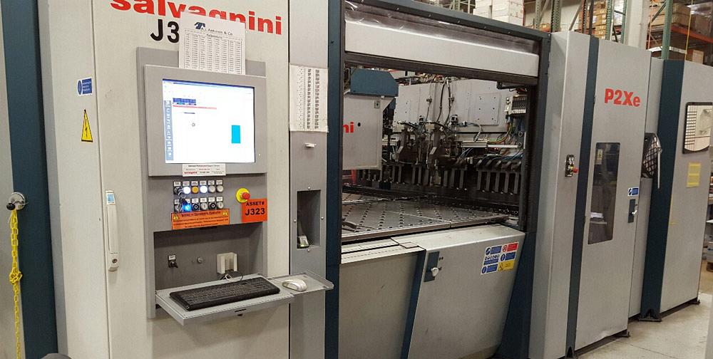
Figure 4
A.J. Antunes’ bending department increased its bending throughput dramatically when it purchased its panel bender four years ago. Photo courtesy of A.J. Antunes Inc.
“Eventually all the old press brakes are going to be gone,” Montalvo said. “This really is going to be the new way.”
When St. Louis custom fabricator CR Metal Products purchased its automated bidirectional folding system from RAS Systems, company leadership made it known that if a part could be bent on the system, it would be (see Figure 6).
The fabricator bought a folder because of a contract it had that involved extremely complex forming, including large panels with at least 15 bends in both the positive and negative direction.
“After the initial program, the setup is so quick,” said Mark Chadwick, vice president of operations. “You can do a one-piece run followed by a five-piece run. As fast as you can feed the next part into it, it can be ready to run the next job. And long-run jobs are great also, because the system processes parts typically much faster than a press brake.”
Chadwick added that for first-time prototypes, initial programming and tryout can take time for complex parts. “But even if the programming time is a little long, we want to run that sample the way we run production, to prove that the folding machine can run the part. Folders can do things that press brakes can’t do, certainly with standard tooling, while press brakes can do things that folders can’t do.”
Say the shop needs to form a 1-in. flange followed by a 3⁄8-in. flange. “In a press brake, this would require a 3⁄8-in. gooseneck die with an inch relief in it,” Chadwick said. “A folder, though, can form that geometry easily. It also can do bumpbends efficiently and consistently.” He added that the company commonly forms hinge curls—which usually require special form tools on the punch press or press brake—on the folder without special tooling.
CR Metal also invested in modified clamping beam tooling with relief sections machined in the bottom, which allowed the tools to hold parts that normally wouldn’t be formed on a folding system. This included blanks that had embosses and other elements created by form tools in the punch press. And even if certain forms don’t clear, the machine may still be able to fold the part, depending on the application requirements.
“The [clamping beam] tools don’t necessarily have to hit the material with full gripping power,” said Chadwick. “The tool can come down and set right on a [previously formed] feature.” This arrangement works only for certain jobs, like those calling for wide-radius bends, Chadwick explained, but it’s an option that doesn’t require an additional tooling investment.
The shop doesn’t send any part to the folder that’s less than 1 foot wide, with 6 in. of open space after forming so the manipulator can grab the part and slide it out of the workspace. Parts need to be a certain size for the articulated-arm robot to load them.
The machine is limited to 14-gauge mild steel and thinner, based on the width of the bending blade on the beam, though it can handle thicker material with different tooling. The blade is wide enough to handle most thicknesses that flow through the shop, yet narrow enough to access small offset forms and narrow inside flanges.
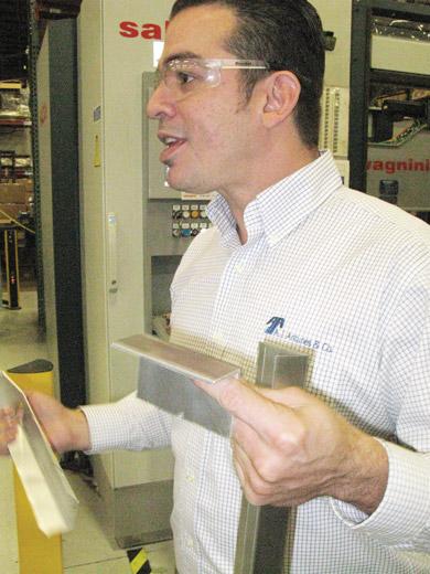
Figure 5
During an FMA event tour three years ago, Jorge Montalvo, fabrication manager at A.J. Antunes, demonstrated how his team forms multiple parts microtabbed together on the panel bender. After forming, the operator then removes the sheet and snaps the parts apart.
When CR Metal purchased the machine almost a decade ago, it loaded it to full capacity and then some. At the time, though, the company also happened to be reorganizing the shop floor into manufacturing cells. Following an improvement methodology called quick-response manufacturing (QRM), the custom fabricator organized its shop floor into workcells: a laser or punch press was grouped with a press brake, hardware insertion, tapping, spot welding, and other secondary processes. Each cell handles various families of parts, grouped by thickness and geometry.
This worked wonders, but it also conflicted with the idea of everyone sending all the parts they could to the folder. Sure, the folder could complete certain parts within seconds, but those parts also sat in queue for hours in front of the folding cell, waiting their turn.
Today the company follows a different philosophy. The folder is part of a cell that handles large parts as well as complex forms that would be difficult or impossible to make on the press brake, at least without special tooling.
Say a job is released to a certain cell with a laser feeding several press brakes. The cell happens to be heavily loaded; are cut parts brought over to the folder? Not anymore. As Chadwick explained, moving some jobs to the folder introduces complexity to the routing, which adds variability and unpredictability to part flow.
After years of experience with QRM, managers have found that moving parts out of a cell to another machine for bending, and then back to that cell for hardware and further processing, almost always takes longer than if the part stayed in the cell and moved from one machine to the next. Chadwick added that this includes not just the time the part spends being shuttled back and forth, but also the time spent managing the more complex routing.
“The cost of managing this would outweigh any speed gained by sending more parts to the folding center,” he said.
All this follows the QRM philosophy: When people in the manufacturing cell start a job, they take ownership of it and carry the work through multiple processing steps. “Our folding center is really tied to our TRUMPF laser, so that laser feeds that machine,” Chadwick said. “So for the other cells that have press brakes, we try to keep parts in the cells in which they are cut.”
The shop still uses its folder to the fullest extent. Chadwick recalled running a sample part with a closed hem, several bends with a 1⁄16-in. radius, and then a larger 0.5-in. radius form on the other side.
“The folding system does this all in one setup. On a press brake, this would require three or four setups. The part is big enough that we couldn’t set it up in a stage-bend either. On the folder, we hit go, and the first part is typically a good part.”
Atlanta’s Tie Down Engineering doesn’t seem like the perfect fit for folding. The company produces various trailer, marine, and roofing products and has a growing custom fabrication division that produces parts for defense, transportation, and other industries. It has built a reputation for fabricating high-tensile-strength materials—and overcoming all the forming challenges these materials create
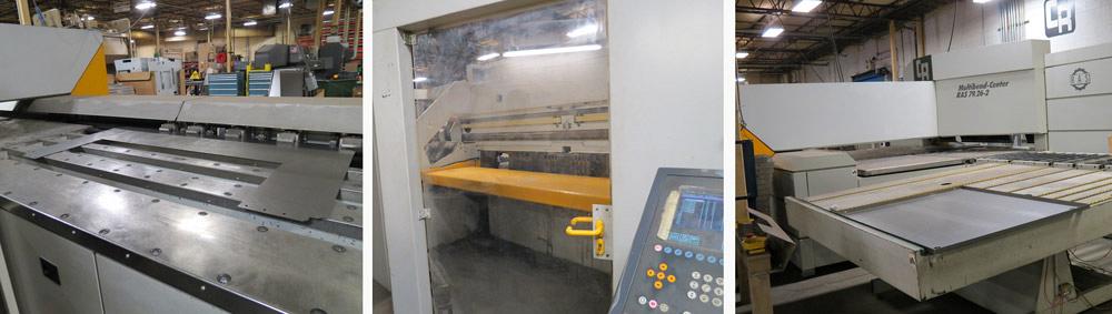
Figure 6
A robot feeds blanks into CR Metal’s automated folding center. Many forms made on the folder wouldn’t be possible on the press brake without special tooling.
Nevertheless, earlier this year the company invested in bidirectional folding. But it’s folding on a large scale. With a sufficient bending-blade width on the folding beam, the folder—a Schroeder machine from MetalForming Inc.—can form material up to 0.25 in. over the entire 10-ft. bed.
“We actually had no specific [customer] requirement for it,” said Sloan MacKarvich, president of Tie Down’s Industrial Laser Solutions, the company’s custom fabrication division. But the manufacturer is already finding work for the new system (see Figure 7). Along with production parts, MacKarvich said that the machine will help tremendously with some R&D the fabricator is doing with certain customers.
“To be successful with something like this, we can’t just say, ‘OK, what do I have on a press brake to put on this machine?’ The question is, ‘What can we do with a folder that we cannot do with a press brake?’”
So said Warren Van Nus, vice president of Omega-Tek, Tie Down’s new R&D arm that specializes in projects in the automotive, defense, and energy industries. Van Nus pointed to a redesigned product with one positive bump-bent radius followed by a negative bump-bent radius. The large plate would require an operator on a press brake to flip midway through, and gauging it right would be extremely challenging if not impossible. The bidirectional folder, on the other hand, has no problem at all.
MacKarvich pointed to the company’s massive clamping beam tooling that allows for 19.5-in.-high flange depths. The size of these tools made it almost a given that the shop needed to choose a folder with automatic clamping beam tool changes. The shop’s system has robotic manipulators that grab, replace, and rearrange clamping beam tools for different bend lengths.
The company also invested in several bending blade widths: a thick blade designed to bend up to the machine’s 0.25-in.-thick capacity, and a narrower blade to use for thinner material and accessing narrow offsets (see Figures 1-3).
MacKarvich conceded that the tooling investment was expensive, especially when you compare it to conventional press brake tooling—but you also don’t need many folding tools to form a wide variety of parts. “For this reason, when we chose our tools, we needed to find ones that were as versatile as possible.”
To this end, the company invested in mechanically lifted corner tools that allow the folding machine to form a box bend in which there are already return flanges on the sides (see Figure 1). Conventional clamping beam tooling would collide with those return flanges. The mechanically lifted corner tools have wings on the side that spread when pressure is applied, allowing the tool to reach to the edge of the sheet—what will become the inside corner of the box.
These days fabrication operations are expanding their bending capabilities. Few brake operators enjoy lifting a large, heavy workpiece high into the air to form an edge flange. If they do enjoy it, their backs certainly don’t.
Today shops are investing in panel bending and folding not only to improve ergonomics, but also to improve throughput and bend forms that just wouldn’t be practical on the press brake, at least without special tools.
With greater throughput than ever in sheet metal cutting, the bending department at many fab shops may well change dramatically in the coming years. Panel bending, folding, and press brake bending with ATC all give a hint at where the bending department may be headed.
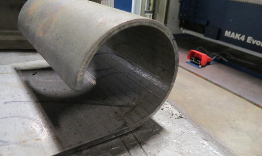
Figure 7
This bumped radius was created by Tie Down Engineering’s new bidirectional folding machine with automated clamping beam tool change.


The Fabricator is North America's leading magazine for the metal forming and fabricating industry. The magazine delivers the news, technical articles, and case histories that enable fabricators to do their jobs more efficiently. The Fabricator has served the industry since 1970.
start your free subscription
Easily access valuable industry resources now with full access to the digital edition of The Fabricator.

Easily access valuable industry resources now with full access to the digital edition of The Welder.

Easily access valuable industry resources now with full access to the digital edition of The Tube and Pipe Journal.

Easily access valuable industry resources now with full access to the digital edition of The Fabricator en Español.
In this episode of The Fabricator Podcast, Caleb Chamberlain, co-founder and CEO of OSH Cut, discusses his company’s...


