


Contributing Writer
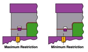
Figure 1
Obtaining a wrinkle-free part and the desired percentage of stretch in a deep drawn part sometimes can be very frustrating and time-consuming. Wrinkles, fractures, loose metal, buckles, and oil canning are everyday problems in the die build and stamping industry.
Addressing these difficulties requires a good understanding of metal flow and how it is affected by draw beads, step beads, and draw bars, as well as the effects of part geometry. This article focuses on the principles of specifying, designing, and troubleshooting these four basic elements.
Draw beads are rib-like projections mounted on either the binder or the draw ring surface that restrict and control metal flow into the die cavity and over the punch of a draw die. Simply put, draw beads act as speed bumps for material traveling into the die cavity.
Imagine yourself in your car traveling at 55 miles per hour. Ahead, you see a speed bump with a gradual, gently flowing radius. Unless you are a stunt driver, chances are that you would decelerate before contacting the bump to allow yourself to pass over it smoothly.
If instead of a speed bump in the road you saw a large cement curb ahead, you most likely would brake hard so that you could drive very slowly over the obstacle. If the curb were too high, you might elect not to go over it at all.
Your decision on how fast to travel over either obstacle is based, in part, on the obstruction's geometry. Draw beads use the same basic principle to control material that is pulled into a die cavity by the vertical action of a stamping press.
Draw beads force material to bend and unbend before entering a die cavity. This action creates a restraining force on the sheet metal, which causes the material to enter the die cavity at a reduced rate and at a reduced volume. The height, shape, and size of a draw bead and bead cavity govern the amount of restrictive force generated. A sharp draw bead and cavity radius decrease metal flow, while a large draw bead and cavity radius allow material to flow more freely (see Figure 1).
A step bead is very similar in function to a conventional half-round draw bead, except that it has a different shape. Step beads typically are located on the outside perimeter of the binder punch opening. This location allows for optimal metal flow control close to the draw punch and affords an opportunity for material savings.
Step beads can be set with less force than can conventional half-round draw beads, and often they reduce the amount of strain hardening that occurs during the bending and unbending process. Strain hardening is reduced primarily because material is subjected to less bending and unbending when step beads are used (see Figure 2).
Draw beads can be machined, welded, or inserted on top of or into the draw ring or binder surface of a draw die. Because draw and step beads usually are subjected to a great deal of abrasive and adhesive wear, they must be made from very wear-resistant tool steel. In addition, they must blend gradually into the surface on which they are located. This blended transition gradually changes the restrictive force, reducing the possible shearing or tearing action of the "rind" or addendum areas of the drawn shell.
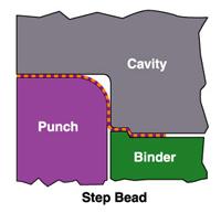
Figure 2
Determining the best location for a draw bead is a judgment call based primarily on part geometry. Deeper areas of a drawn shell require more material flow; shallow areas of the shell consume less material. Material consumption between the two surfaces can be estimated using length-of-line analysis.
To keep excess material from flowing into the shallow areas of a part, draw or step beads must be designed in the feeding areas of the binder surface. Experimenting with sandpaper or grit cloth between the binder and draw ring surface can help determine the best location for a draw bead. Because of their abrasive natures, the materials act as grippers to help hold material and prevent it from going into the die cavity, thus mimicking draw beads.
Another experimental process to help determine the best location for a draw bead involves increasing the blank size in the proposed area. The additional material between the binder and the draw ring increases the blank restraint force and indicates where a draw bead can be substituted.
Draw bars are bumps or semirounded "miniposts" that are used extensively in Class A surface stampings, for which stretch and dent resistance are critical for achieving an acceptable appearance. They differ from draw beads in that they are part of a draw punch rather than the die.
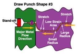
Draw bars must be placed outside the final part geometry and typically are in the more shallow sections of a drawn part (see Figure 3). They have two main functions:
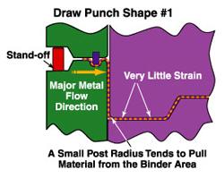
The shape of the draw punch often dictates the amount of stretch that can be achieved during the drawing action. Simply put, wherever there is a large male radius on the punch or die cavity, the metal will stretch and flow. Small radii tend to lock off or limit stretching and flowing of material. When parts are designed properly, extensive flow and stretch can occur in both the product and from the binder area.
The draw punch in Figure 4 has a small radius on the punch. This small radius forces material to be pulled primarily from the binder area. If the draw ratio is extreme, the part most likely will split in the vertical wall of the drawn shell. Because the small radius on the punch does not promote material flow, little or no stretch will occur in the center product area of the part.
The draw punch in Figure 5 has a large radius on the punch. This larger radius pulls and stretches material from both the binder and the product areas. This punch shape is most desirable when trying to achieve overall maximum stretch in the entire product area.
In another possible arrangement, the draw punch has a large radius on the perimeter of the shell and a small radius on the inside profile of the punch cavity. In addition, the die cavity post has a large radius. This product shape allows material to be pulled from both flat areas of the part and from the binder area.
Finally, the draw punch could have large radii on the outer profile of the punch and the inner profile of the punch cavity. The cavity has a small radius. This product design tends to pull and stretch material from the outer flat portion of the product area, as well as from the binder area.
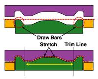
Figure 3
Understanding the basic principles of obtaining stretch and eliminating wrinkles can prove to be most valuable when troubleshooting drawn parts.
All too often, draw beads are used in an attempt to obtain stretch and reduce wrinkling when the basic part shape is not conducive to stretch and could be altered without affecting fit or function. Successful stretch can be obtained through the use of draw beads, draw bars, and changes in part and addendum geometry.


The Fabricator is North America's leading magazine for the metal forming and fabricating industry. The magazine delivers the news, technical articles, and case histories that enable fabricators to do their jobs more efficiently. The Fabricator has served the industry since 1970.
start your free subscription
Easily access valuable industry resources now with full access to the digital edition of The Fabricator.

Easily access valuable industry resources now with full access to the digital edition of The Welder.

Easily access valuable industry resources now with full access to the digital edition of The Tube and Pipe Journal.

Easily access valuable industry resources now with full access to the digital edition of The Fabricator en Español.
In this episode of The Fabricator Podcast, Caleb Chamberlain, co-founder and CEO of OSH Cut, discusses his company’s...


