


Contributing Writer
The problems associated with forming high-strength steel often are created during the design stage, when products are designed in such a way that they cannot be manufactured using conventional stamping methods. Or the product requires numerous or special offline operations, such as annealing or normalizing. This article discusses a few of the most important part characteristics that need to be addressed during the design stage.
Products often are designed to meet certain visual or functional shape requirements. After the product is designed, a steel type that has enough strength to achieve the function is chosen. This process sometimes has serious pitfalls. Both strength and geometry are critical to a part's success. You must consider the physical strength requirements of the part while designing it, because the product or part shape often dictates the type of metal that can be used. For example, a very deep-drawn shape may be the required geometry for the product, and the strength requirement may also be very high. The question to ask yourself when designing the product is Can the deep-drawn shape be made with high-strength steel?
Avoid designing the geometry and then selecting a steel strength. Instead, consider the strength requirements of the part and try to design a part around the steel's formability characteristics.
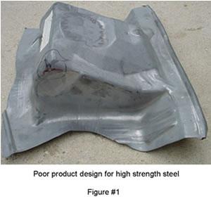 |
Figure 1shows an example of a poor product design for high-strength steel. This part shape is both very deep and requires an abundance of stretch.
High-strength steel has reduced stretch distribution characteristics, making it less stretchable and drawable than conventional lower-strength steels. Stretch distribution characteristics determine the steel's ability to distribute stretch over a large surface area. The better the stretch distribution, the more the steel can stretch over the draw punch to create the final geometry.
Stretch distribution affects not only stretchability, but also elastic recovery, or springback, and the metal's total elongation. For example, 40X high-carbon cold-rolled steel has a yield strength of approximately 44,000 pounds per square inch (PSI). Along with this high strength comes poor stretch distribution that results in a total elongation of 17 percent (2 inches minimum). Compare this to deep drawing quality (DDQ) cold-rolled steel with a yield of approximately 26,500 PSI and with good stretch distribution characteristics that result in a final elongation of roughly 44 percent.
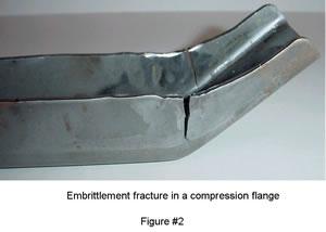 |
High-strength steels often contain a lot of magnesium. Magnesium, which is used in metal jail bars, helps to give the steel its increased strength. Unfortunately it also causes the steel to become very brittle, resulting in ductility or embrittlement fractures. These fractures, improperly named compression, are fractures or cracks that result when the metal has been severely compressed, embrittled, work-hardened, and relaxed in tension. Figure 2shows an embrittlement fracture.
The limiting draw ratio (LDR) is perhaps one of the most important items to consider during product design. Because high-strength steels have poor stretching characteristics, it is important to be able to obtain the part geometry through the process of plastic flow.
The draw ratio is defined as the direct relationship between the draw punch and the blank edge. If the blank edge is too far from the draw punch, the metal will not flow inward and the metal will be forced to stretch. Metals with poor stretchability, such as high-strength steel, will be subject to failure. Metals with good stretchability will be less likely to fail.
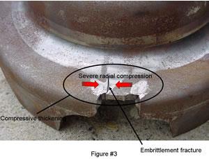 |
When designing deep-drawn parts, keep in mind where the forming punch contacts the metal relative to the blank edge. Very deep forms far from the blank edge are risky and may require additional preforms. This will add additional cost to both the tooling and product. Also avoid sharp profile radii, because they will force the metal to compress severely before flowing inward. This severe compression may cause embrittlement fractures to occur. Remember, areas that will be in compression will also have a great resistance to flow.
Figure 3shows an embrittlement fracture in an area of severe compression. Pay strict attention to the LDR in these areas. If the part is a contoured deep-drawn part, it most likely will require the use a specially profiled blank to obtain its part shape through plastic flow. This special blank shape helps to maintain the draw ratio and helps to prevent part splitting and fracturing.
 |
Remember that a small profile radius not only may cause an embrittlement fracture, but also can reduce the metal flow inward. Metal that is not in radial compression has very little resistance to flow. For example, the side walls of a deep-draw box have very little resistance to flow and are not as sensitive to the limiting draw ratio; however, the corners of the box are in radial compression. This radial compression causes a resistance to flow. Increasing the radius size reduces the amount of compression, resulting in increased metal flow inward.
Figure 4shows a typical box drawn from a rectangular blank. The more the radius resembles a straight line, the less the resistance to flow. Avoid using sharp profile radii, especially in areas that are to be deep-drawn.
Avoid steep or vertical wall angles in areas that defy the draw ratio when possible. The exception to this rule is, of course, when you have an acceptable draw ratio. Open wall angles allow maximum product stretch as well as a longer length of line for the metal to be stretched. They also help to reduce the tendency for splits and fractures, as well as help to promote better strain distribution. Figure 5shows both poor and good wall angles for a product designed with high-strength steel.
 |
Use very large, liberal radii whenever possible. A large radius allows the metal to flow and to stretch to its maximum capability. Avoid sharp radii, especially in deep drawn products. Using too small radius may result in splitting or require additional preforming operations. Large dome shapes often are desired.
This article discussed only a few of the most commonly ignored product design features. The extent to which you apply these concepts is controlled largely by the material's strength and forming characteristics. Avoid designing high-strength steel parts the same way that you design low-strength parts. Design your parts to be made through the process of plastic flow rather than stretch. It's a fine balancing act between product geometry and formability, but understanding a few basic formability principles will help you design products that are both strong and functional.


The Fabricator is North America's leading magazine for the metal forming and fabricating industry. The magazine delivers the news, technical articles, and case histories that enable fabricators to do their jobs more efficiently. The Fabricator has served the industry since 1970.
start your free subscription
Easily access valuable industry resources now with full access to the digital edition of The Fabricator.

Easily access valuable industry resources now with full access to the digital edition of The Welder.

Easily access valuable industry resources now with full access to the digital edition of The Tube and Pipe Journal.

Easily access valuable industry resources now with full access to the digital edition of The Fabricator en Español.
In this episode of The Fabricator Podcast, Caleb Chamberlain, co-founder and CEO of OSH Cut, discusses his company’s...


