


Contributing Writer
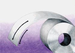
Figure 1Object
Fabricators encounter various shape defects in flat-rolled ferrous and nonferrous strip, some simple and some complex. How do these defects originate? What methods and machines can fabricators use to correct them?
Simple shape defects are characterized by length variations across the thickness of the strip.
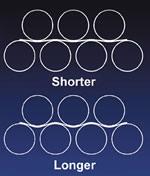
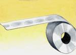
Coil Set. Coil set is the most basic and common of all shape defects. It is caused by a length differential from the top to bottom surface of the strip in the lengthwise direction (see Figure 1). It can come from a previous bending operation (for instance, the exit passline roll in a slitting line is notorious for putting in reverse coil set) or just from coiling the coil in a cold mill, a hot mill, or even on a tension level line.
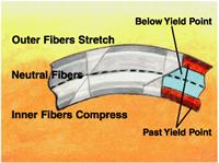
This condition can be corrected by reverse-bending the material, which stretches the short surface and compresses the long surface. For this correction to be permanent, the material must be bent past its yield point, which is commonly referred to as its yield diameter. The yield diameter of a material can be calculated using the following formula:
Dy = tE/Y
where: Dy = yield diameter, inches
t = material thickness, inches
E = modulus of elasticity, pounds per square inch
Y = material yield strength, PSI
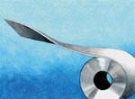
Figure 3Object
The modulus of elasticity is a basic material property that defines its stiffness. A high number indicates the material is stiff, while a low number indicates it is not. Steel has a modulus of elasticity of about 30,000,000 PSI and is considerably stiffer than aluminum, which has a modulus of elasticity of 10,000,000 PSI.
For example, an aluminum strip that is 1/8 in. thick with a 40,000-PSI yield strength must be bent to a 31-1/4-in. diameter to reach the point at which any further bending will cause permanent set. On the other hand, a 1/8-in.-thick, 40,000-PSI-yield-strength steel strip would need to be bent only to a 93-3/4-in. diameter to reach the same plastic point.
To have the same effect, aluminum must be bent to a much tighter diameter than steel, which requires more work and more power. If the steel in this example had a 120,000-PSI yield strength, the yield diameter would equal 31-1/4 in., so high-yield-strength products also require tighter bends and more work and power.
Coil set typically can be corrected by applying a small reverse bend, which can be performed by a spread-center flattener. A spread-center flattener generally can create only shallow bends. Shallow bends also can be produced at the exit end of a close-center flattener or leveler, so they, too, can correct this type of defect.
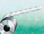
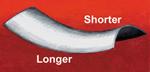
Crossbow. Crossbow is the second most basic of all shape defects. It also is caused by a length differential from the top to the bottom surface of the strip. It is most recognizable in true hot-rolled material with scale that has never been opened.
Like coil set, crossbow is in the direction of the bend, but the bend direction is across the width of the strip (see Figure 2). Crossbow is related to coil set by Poisson's ratio, which is approximately equal to 0.3 for steel and aluminum.
When coil set is pulled out, crossbow appears. To remove crossbow, the reverse bend must be made more severe than it would be to remove the same amount of coil set—effectively three times as great as it would be if the strip could be turned 90 degrees and reverse-bent.
Because crossbow requires much tighter bends to correct than coil set and generally more than can be attained on a spread-center flattener, some people believe that a close-center flattener or leveler is required to correct crossbow. This is not exactly correct, however, because the amount of bend, not the method of bending, is most important.
If the strip can be bent the right amount with a spread-center machine, it will lay flat. However, most spread-center machines are not backed up and will deflect, which can cause edge wave or other problems in the strip.
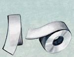
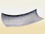
Twist. Twisted strip (see Figure 3) is caused by a length differential from the inner to outer surfaces of the strip, which simultaneously varies across the width of the strip. It can be caused by a side-to-side temperature differential in the hot strip mill. Twisted strip generally requires more severe bending to correct; like crossbow, it can be corrected by "biting in" deeper at the entry end of the machine.
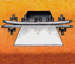
Figure 4Object
Twisted strip has positive coil set on one side and negative (less positive) coil set on the other. This type of defect is readily corrected by the deep mesh of the machine's entry end. This deep mesh turns both edges of the coil to either positive or negative coil set and then gradually reduces the coil to flat as it proceeds out through the tapered mesh of the machine.
It is important to understand the differences between a leveler and a backed-up flattener before discussing complex shape defects. The rolls in a flattener always remain straight, but the work rolls in a leveler can be flexed or shaped by vertically adjusting the height of the independent backup rollers (see Figure 4).
A flattener's rolls always have a neutral setting like a leveler, with all of its backups adjusted flat. A leveler, though, also can have its backups adjusted to close the center of the rolls tighter to the edges (see Figure 5), or vice versa. Work rolls even can be put into multiple curves, depending on the strip defect being corrected.
Roll shaping gives a leveler the ability to stretch material lengthwise in particular longitudinal sections. Flexing the leveler work rolls creates longer path lengths in specific areas of the machine (see Figure 6).
Camber. Camber is a linear length differential from side to side, but not from the outer to inner surface (see Figure 7). It can be caused by misaligned rolls that stretch strip edges or poor rolling mill conditions that cause an unevenly elongated side. Material measuring 1/8 by 72 in. needs only a 0.0006-in. thickness differential from side to side to cause 1/8 in. of camber in a 10-ft. length.
This defect cannot be corrected by a flattener or roller leveler, because these machines have no means to stretch the short side out to the length of the long side. They can stretch or compress only the outer fibers of a material, not the middle fibers (seeFigure 8).
A tension leveler can be used to remove camber from strip. When tension is added to the coil, the neutral axis shifts, allowing elongation of the middle fibers.
Edge Wave. The edge wave defect is characterized by strip edges that are longer than the center. This excess length manifests itself as a wave in the material (seeFigure 9). Edge wave can be caused by overloaded pinch rolls, flattener rolls, feeder rolls, slitters, mill rolls, or coil cradles.
While edge wave probably is the easiest defect to cause, it also is one of the easiest to remove. For removal, the center portion of the strip is stretched to a length equal to the longer edges. This is accomplished by making the path length through the leveler longer in the center by applying the center independents (see Figure 4).
Edge wave caused by a slitter, however, is very difficult to remove; slitter edge wave tends to be a very localized edge defect, and it is difficult to get enough shape in the leveler rolls to remove it. Slitter edge wave is easily recognizable, as it is generally a very tight edge wave that is concentrated toward the edge of the strip.
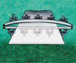
Figure 5Object
Center Buckle. Center buckle is the opposite of edge wave in that the center portion of the strip is longer than the edges (see Figure 10). Center buckle often comes from mill rolls, but overly crowned pinch or feed rolls are just as likely to cause it. It can be corrected by closing down the outside independents (see Figure 5).
Quarter Buckle. Quarter buckle is strip with two distinct buckle patterns in from the edges with a tight section down the center. Quarter buckle, like center buckle, can be caused by mill rolls. This defect can be corrected like the others, by closing down the independents over the tight, unbuckled portions of the strip.
Saddle. Saddle is a combination of negative coil set and positive crossbow, or vice versa. It is a shape formed by an inside sector of a torus. In addition to length differentials between the top and bottom surfaces of the strip, it also has a length differential from its center to its edges (see Figure 11).
[image13]Correcting this condition begins with a significant plunge at the entry end. This forces the coil set and crossbow into the same direction so they can be worked out by the tapered nest. However, as this material is flattened, the outside edges of the strip are longer than the center. This leads to an edge wave condition that is corrected by applying the center independents.
Dish. Dish is an unusual condition that has both negative coil set and negative crossbow (see Figure 12). It can be an extremely difficult condition to correct because a typical leveler's rolls are arranged to turn material up, not down. The best thing to do is to bite in the entry end of the machine fairly deeply to attempt to remove the coil set and crossbow. The end independents also must be applied because as this material is flattened, it will manifest a center buckle just opposite the saddle defect.


The Fabricator is North America's leading magazine for the metal forming and fabricating industry. The magazine delivers the news, technical articles, and case histories that enable fabricators to do their jobs more efficiently. The Fabricator has served the industry since 1970.
start your free subscription
Easily access valuable industry resources now with full access to the digital edition of The Fabricator.

Easily access valuable industry resources now with full access to the digital edition of The Welder.

Easily access valuable industry resources now with full access to the digital edition of The Tube and Pipe Journal.

Easily access valuable industry resources now with full access to the digital edition of The Fabricator en Español.
In this episode of The Fabricator Podcast, Caleb Chamberlain, co-founder and CEO of OSH Cut, discusses his company’s...


