


Contributing Writer
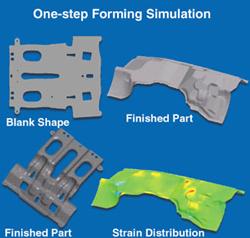
Figure 1Object
Tremendous advancements have been made in sheet metal stamping during the last decade. Even during my short 22 years of tooling experience, I have seen dies designed with a pencil and a drafting board; with a computer; with solid modeling; and with real-world 3-D methods.
I've seen steel cut with saws, oxyacetylene, and plasma torches, to CNC machining centers, waterjets, lasers, electrical discharge machines (EDMs), and CNC plasma arc cutting machines. The speed at which this equipment can perform also has increased, from cutting steel a slow 1 inch per minute (IPM) to 600 IPM.
Such high-tech tools allow today's dies to be processed, designed, and built in a fraction of the time than previously required.
Perhaps one of the most valuable high-tech tools introduced in the last decade or so is forming simulation. Forming simulation is a special type of finite element analysis (FEA) that simulates metal being deformed by almost any deforming method.
One of the biggest uses for this technology is the stretch and deep drawing industry. This specific type of FEA typically is referred to as drawing simulation software. It also is called a one-step solver, inverse solver, or virtual press.
Forming simulation software offers numerous advantages for toolmaking.
Other benefits of forming simulation include:
In addition, simulation software is designed to show details of the design, such as:
The software also helps to identify possible tooling changes that would result from:
Remember that FEA software does not design the die for you, but rather shows you the results of your die design based on the data you input into the computer. A lot of people invest in this technology thinking that it will design the die for them. Not true.
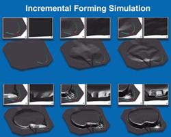
Figure 2Object
The initial cost of FEA software can be substantial, so you need to compare that cost to your anticipated cost and efficiency savings over the long term. It would be surprising if your calculations do not reflect a good return on investment (ROI). I know toolmakers who have saved millions of dollars using this software.
Also, significant training is required to run the software properly. An average training period might be about two months if training is done every day. However, the amount of training needed depends on the person learning the software. Using the software and training appropriate personnel to run it effectively can provide a quick ROI.
The person operating the software will be creating and inputting the die geometry and is simply using the computer as a tool. Therefore, my recommendation is that you train a person with a great deal of formability expertise, such as a product designer, tool designer, process engineer, or diemaker. It's much easier to train a person who knows about forming and drawing how to run a computer than it is to train a computer operator how to design and process deep-drawing and forming dies.
Certain kinds of information must be input into the computer for the software to be efficient, including:
Forming simulation can help you design and build both your parts and your tooling. The real glory of forming simulation is that it does so in the virtual world, before the tool is actually built. Die geometry changes can be made in minutes instead of hours—no need for welding, grinding, or proof prototype tooling.
Forming simulation is very accurate. However, to achieve the same results after the tooling is actually built, the same variables must be achieved that were used in the simulation.
Today's simulation software doesn't tell you how to design your dies—it just gives you the result of your design. Tomorrow, who knows? It might just design the die for you. As for me, I wish they'd come up with a program that could help me put my thoughts on paper a little easier. Best of luck!


The Fabricator is North America's leading magazine for the metal forming and fabricating industry. The magazine delivers the news, technical articles, and case histories that enable fabricators to do their jobs more efficiently. The Fabricator has served the industry since 1970.
start your free subscription
Easily access valuable industry resources now with full access to the digital edition of The Fabricator.

Easily access valuable industry resources now with full access to the digital edition of The Welder.

Easily access valuable industry resources now with full access to the digital edition of The Tube and Pipe Journal.

Easily access valuable industry resources now with full access to the digital edition of The Fabricator en Español.
In this episode of The Fabricator Podcast, Caleb Chamberlain, co-founder and CEO of OSH Cut, discusses his company’s...


