


Contributing Writer
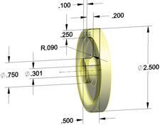
Figure 2aTo model the wheel quickly, sketch only one-quarter of it. Some of the dimensions are known from the catalog, and others are just guesses.
As promised last month in Part III (Precision Matters, March 2010, p. 28), we're going to continue modeling the Shashlik Grill components, such as the wheels, axles, and retaining caps. Our goal is to maximize our efficiency in modeling the parts that are going into our assembly.
(The usual disclaimer: If you're not using the same 3-D CAD software as I am, then you'll have to translate some of the terminology. However, the concept of parametric modeling is widely applicable.)
As a design project evolves from conception to final release, the CAD jockey's emphasis changes from visualization of an inspiration to documentation for production. The bill of materials (BOM) is the ultimate deliverable. Without an accurate BOM, the overall manufacturing process will be chaotic.
Our project is still in the early stages of the design process. We have the basic shape and structure of the components we're going to have fabricated to our specifications. We now need to include some models of off-the-shelf components to finalize the details of our custom parts. Including these components in our CAD model also will automate the production of a BOM.
During the modeling process, a time will occur when including all the fine details of the project is necessary. At some point you will want to include each nut and bolt—everything that goes into the assembly. How do you decide when to delve into that level of detailed modeling?
If the detailed modeling effort detracts from your immediate goal, then postpone the distraction. For example, if your immediate goal is to rough out the basic structure of the product—how many legs, shelves, wheels, and handles—you don't need to fuss with tiny details like selection and modeling of inch or metric hardware.
Another important criterion to use as a guide for level of detail is to consider how the component will be obtained. If the component is available from a catalog—a nut or a bolt, for example—then put minimal effort into modeling it. Focus on modeling the details for the components that will be custom-fabricated.
I like using other people's models (OPM). Does that make me lazy or efficient?
To create the assembly instruction illustration shown in Figure 1, we need several 3-D CAD models. The models for the custom sheet metal legs and shelves, covered in previous columns, are well under way. The axle is a custom part, and it won't take much effort to model it to an exact level of detail. It's just a cylinder, after all.
The wheel and the axle cap present a dilemma. In this project, these items will be purchased as finished goods from a catalog. So our 3-D CAD models for these items really do not need exacting detail.
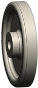
Figure 2bThe sketch in 2a is revolved to create a solid model of half of the wheel.
Occasionally I create placeholder models—3-D CAD models that have no features. All they do is have a file name or description to remind me that, when the schedule permits, I will need to put some detailed effort into them. Such models also work well for items like grease or glue; they are hard to model, but necessary for an accurate BOM.
When the time comes to include an off-the-shelf item in the 3-D CAD model, I first look for ready-to-use models. I tend to gravitate toward suppliers that offer online libraries of models that represent their products in a useful way. I need the external surfaces, weight, and mounting or attachment details. I want models that are updated along with immediate pricing and availability. My preference is to visit the supplier's Web site.
As examples, McMaster (www.mcmaster.com) and Reid Supply (www.reidsup ply.com) offer free 3-D models for most of the hardware items that they sell. On those occasions when I've requested a model that wasn't immediately listed, they have responded very promptly.
In our axle cap example, a ready-to-use 3-D CAD model is available online.
Web sites that specialize in 3-D CAD libraries can be useful, at least as a starting point for a CAD model. As examples, consider 3-D Content Central (www.3dcontent central.com) and TraceParts (www.traceparts.com). While free is good, sometimes the commercial libraries have better levels of accuracy, detail, and relevance.
For this project, we've selected a wheel that is readily available. That's the good news. The bad news is that we need to make our own model for this off-the-shelf item.
Figures 2a, 2b, and 2c show one technique for modeling the wheel. In Figure 2a, one-quarter of the wheel is sketched and revolved. Many of the dimensions came from the catalog, but not all. I made some educated guesses for the missing dimensions. If necessary, we can always buy a sample and reverse-engineer it to eliminate the guesswork.
Figure 2b shows the resulting half of a wheel from the revolved body. In Figure 2c, the half wheel has been mirrored to create the full 3-D model.
As usual, this kind of part can be modeled several different ways. In this case, I was striving for quickness over all other considerations.
In Part V of this series, we'll finish up the details of the wheel and axle—maybe add a bushing. Most important, we'll start assigning part numbers and finalizing our file-naming scheme.
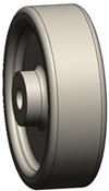
Figure 2cThe body in 2b is mirrored to create the finished wheel.
Keep in mind that this top-down modeling technique we're using is not the only way to do this work. It may not even be the best way in every situation. However, when it comes to virtual prototyping, it is efficient to use parametrically driven features. It takes some time to set up initially, but it will pay off later by speeding the revision process. The use of reference geometry to control parametric features reduces the complexity of figuring out what drives what.
Gerald would love to have you send him your comments and questions. You are not alone, and the problems you face often are shared by others. Share the grief, and perhaps we will all share in the joy of finding answers. Please send your questions and comments to dand@thefabricator.com.


The Fabricator is North America's leading magazine for the metal forming and fabricating industry. The magazine delivers the news, technical articles, and case histories that enable fabricators to do their jobs more efficiently. The Fabricator has served the industry since 1970.
start your free subscription
Easily access valuable industry resources now with full access to the digital edition of The Fabricator.

Easily access valuable industry resources now with full access to the digital edition of The Welder.

Easily access valuable industry resources now with full access to the digital edition of The Tube and Pipe Journal.

Easily access valuable industry resources now with full access to the digital edition of The Fabricator en Español.
In this episode of The Fabricator Podcast, Caleb Chamberlain, co-founder and CEO of OSH Cut, discusses his company’s...


