


Contributing Writer
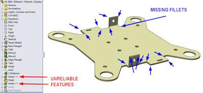
Figure 1: This is the 3-D CAD model that we inherited for this project. Note several problems.
Sometimes it’s important to keep the laser cutting machine in the shop happy by leaving pointy corners out of the design.
In this article we discuss a method for creating a functional snapshot of a concept 3-D CAD model and using it to refine the design for manufacturing. In this case, we want to fillet all of the sharp edges around the perimeter of the part, which makes the laser cutting go faster. In particular, we want to add rounded bend reliefs near the bends.
Before we go any further, let’s start with the usual disclaimer that we’re examining functionality that is unique to SolidWorks®.
In Figure 1 we see the starting point—a 3-D CAD model that has broken external references. The model is missing many fillets, but most of those are easy to add. However, two fillets that are needed near the bends are a challenge.
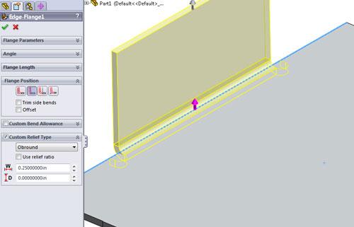
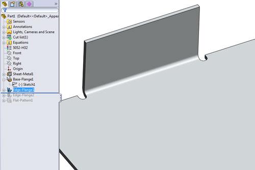
It would have been better if the concept model had used the technique shown in Figure 2a—obround bend reliefs. To demonstrate an easy way to create obround bend reliefs:
The results of setting up an obround bend relief are shown in Figure 2b. By using the “custom” options, we have a feature that is very easy to update if a different size is needed in the future.
The trick is to apply that good modeling technique to the starting model from Figure 1. Were it not for the dangling external references, we might consider revising the model. However, a quick glance at the modeling history in the Feature Manager tells me that it might be quicker and safer to apply FeatureWorks® as part of the solution.
We are going to export our starting model as a “dumb solid,” import it back into SolidWorks as a dumb solid, and add some sheet metal features. Presto! We now have great bend reliefs and a model that has no dangling external features.
By “dumb solid” I mean a 3-D CAD model that has no parametric links or modeling history. A dumb solid doesn’t have much that can be edited, accidentally or otherwise.
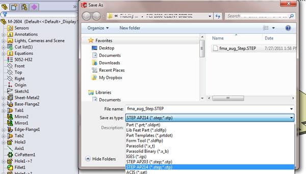
Exporting is accomplished with Save As and then selecting a file type—as shown in Figure 3. In this example, I’m using STEP—the modern version of IGS—but feel free to experiment with other CAD file exchange formats. A situation may arise that one works better than another.
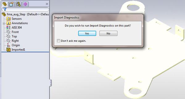
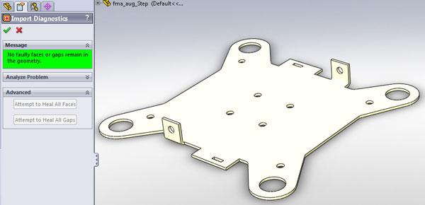
After saving the original 3-D CAD model as a STEP format file, we use SolidWorks to open the STEP file. As the import process nears completion, the Import Diagnostics tool (Figure 4a) gives you an opportunity to verify that all of the surfaces in the model still knit to form a solid. Because we intend to edit the model, we want a clean starting point. The Import Diagnostics tool will help us do that. After clicking Yes, we arrive at Figure 4b, where we find a faulty face in the model.
After clicking on Attempt to Heal All, we arrive at Figure 4c. In this example, the system was able to repair all problems automatically .
A Very Valuable Add-in
FeatureWorks is an add-in for SolidWorks. Not all subscription license agreements include FeatureWorks. If it does not appear in the list of available add-ins, you have my sympathy.
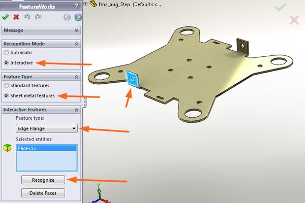
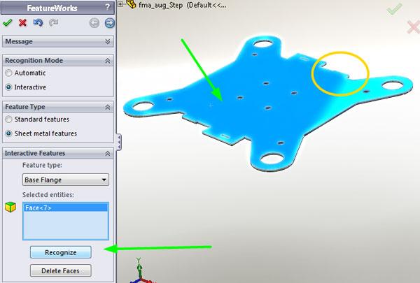
With the FeatureWorks add-in loaded, launch the Recognize Features tool (Figure 5a). Several mouse clicks work well in this example:
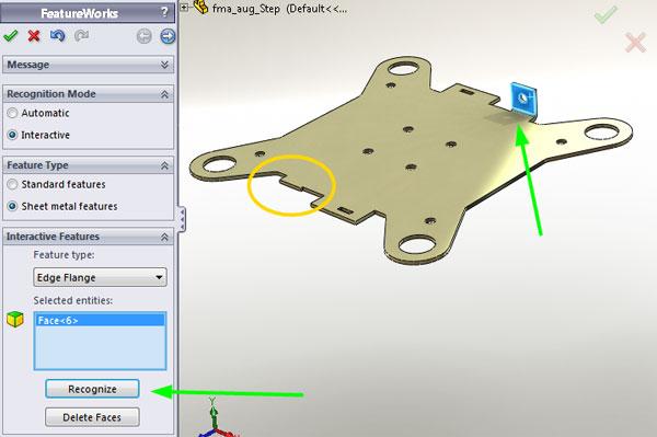
As the features are successfully recognized, they disappear from the preview in the graphics window. In Figure 5b you see that the recognized flange from Figure 5a has vanished due to the options I’ve set up on my copy of FeatureWorks.
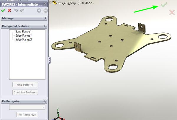
Next, select the other flange and then click on the Recognize button again. Next, we select the Base Flange as shown in Figure 5c. Change the Interactive Feature Type from Edge Flange to Base Flange using the drop-down list. Then select a face, and click on the Recognize button for the last time. Because the software doesn’t have any more features to recognize, FeatureWorks shows the intermediate progress report.
In Figure 5d we see the progress report and note the expected feature history—a base flange with two edge flanges and no errors. Let’s hit the green check mark to dismiss FeatureWorks.
Final Steps to Make the Laser Happy
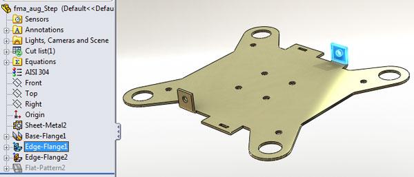
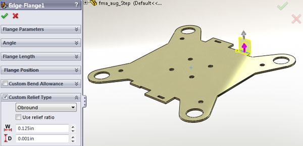
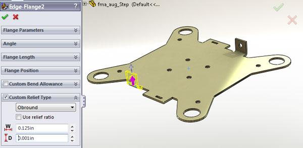
Next, we are going to edit the bend reliefs on the edge flanges. In Figure 6a I’m about to right -click on Edge-Flange1 to set its options. In Figure 6b we see the available options. We are interested particularly in the Custom Relief Type settings:
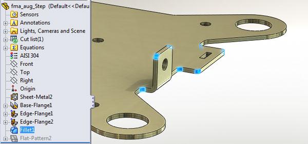
As promised, adding the remaining fillets around the perimeter is easy as shown in Figure 7. I used the FilletExpert and let it find all of the edges for me. But that’s a topic for another column.
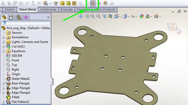
Figure 8 reveals the big payoff—when the part unfolds without any errors. We could have tried reworking the original model with fillets and flats and configurations to manage them, but this is a much more robust solution.
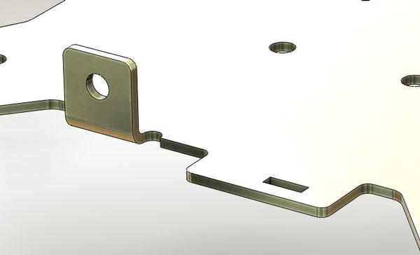
In Figure 9 we see a close-up of the finished part. Because of the options I have set in my copy of FeatureWorks, all of the sketches for the features in this model are fully dimensioned. With a little more time spent in recognizing features, we could have re-created the history for all of the holes as well.
FeatureWorks is very useful if the goal is to re-create a feature history for the model. If all you need is to convert a dumb solid into something that you can unfold—and perhaps change the bend relief style—then the Insert Bends tool may be your best friend. We’ll explore that technique in the near future.
Gerald would love to have you send him your comments and questions. You are not alone, and the problems you face often are shared by others. Share the grief, and perhaps we will all share in the joy of finding answers. Please send your questions and comments to dand@thefabricator.com.


The Fabricator is North America's leading magazine for the metal forming and fabricating industry. The magazine delivers the news, technical articles, and case histories that enable fabricators to do their jobs more efficiently. The Fabricator has served the industry since 1970.
start your free subscription
Easily access valuable industry resources now with full access to the digital edition of The Fabricator.

Easily access valuable industry resources now with full access to the digital edition of The Welder.

Easily access valuable industry resources now with full access to the digital edition of The Tube and Pipe Journal.

Easily access valuable industry resources now with full access to the digital edition of The Fabricator en Español.
In this episode of The Fabricator Podcast, Caleb Chamberlain, co-founder and CEO of OSH Cut, discusses his company’s...


