


Applications Engineer
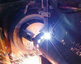 |
Plasma arc cutting has proven to be a process suitable for robots. Automating plasma arc cutting has made the process more flexible for cutting a variety of parts. Robots can perform variations of the process, such as marking and gouging, as well.
Robotic plasma arc cutting can be used for several cutting applications that once were with a conventional 2-D flat table, such as complex shapes and radii on tubes and formed or stamped pieces. A single robot system can be used for plasma cutting and welding or mechanical finishing, which helps reduce the amount of part handling, and overall cycle time. Robotics also can handle the fast travel speeds needed for high-density plasma cutting.
Robotic plasma cutting machines use the same power sources and many of the same torches as hand-held systems and cutting tables. Additional equipment required for the robot includes:
Tool Changer. A tool changer is used when multiple torches or multiple processes are employed. It's mounted to the end of the robot arm and can have multiple toolholders. The tool changer can be programmed to grab certain holders and switch back and forth among them multiple times during a single part cycle.
Toolholder. A typical toolholder can hold several tools. The toolholder location is programmed into the robot. Locations can be anywhere around the robot system, as long as the robot can reach them well enough to slide the tool in and out. It's important to locate the toolholder in the workcell so that access to the different tools isn't restricted and the cables won't become tangled. Pins can be mounted onto a toolholder to hold it in the slots of the tool storage device.
Cable Support Arm. A cable support arm often is used to support the plasma cutting torch and keep it away from the robot arm to reduce the chance of high-frequency current feedback and to keep the cables from getting twisted up around the robot arm. Tool balancers also may be used for this purpose. The arm often is free to swing around so that when the robot goes around the perimeter of its work envelope, the cable is less likely to become twisted or snagged. The support arm also will help improve the torch cable's life by keeping it out of severely twisted situations.
Touch Sensing. Touch sensing can be used to find a part that may move and correct the cut position. This can be done either with a welding torch or with a probe. Often a welding torch already has optional touch sensing that can be turned on when the part needs to be found. A probe mounted separately from the cutting torch also can be used to locate the part and place the cut. Usually the easiest way to find the part is by making sure that the holding fixture locates the part correctly.
Isolation Equipment. Additional isolation equipment may be needed to prevent high-frequency current from changing through the robot control or robot servomotors. The exact items needed will vary with the brand of robot, but generally they include cutting torch insulation, extra grounding in the robot control, isolation pads where the robot is mounted to the system base, and a special isolation coating sprayed on the encoder covers of the servomotors. Also, high-frequency suppressors mounted on the cables might be needed to prevent the high-frequency current from traveling to the robot control. It's important to check with the robot manufacturer for recommendations specific to the robot.
Dirt Shielding. Dirt shielding may be needed to protect the robot arm from dross and sparks. Continually blowing dross and other cutting dirt may shorten the robot arm's life by introducing dirt into its joints. Much of this can be prevented with proper programming techniques that blow cutting debris away from the robot arm, but when this isn't possible, a shield may be necessary between the cutting and the robot arm. Also, smoke removal hoods can be placed on top of the system to reduce smoke levels in the shop.
Many kinds of plasma cutting power sources can be selected based on the application. Simple, inexpensive plasma cutting systems can be used with a robot if the robot's only job is to send the plasma cutter a signal to turn on and off. In this case, the cutting machine controls amperage and gas flow settings. More complex jobs with more than one setting turn parameter control over to the robot. This requires a more expensive cutting system, in which an analog or digital signal is sent back to the plasma cutting power source, telling it to provide multiple power levels for the cutting application. Such a system also can provide gas flow control.
The three main types of torch height control used for plasma arc cutting are:
Using programmed points (no external height control) requires parts consistent enough to be cut via the taught robot path. This often works well on tubing, which varies little in the location of the cut surface so a consistent torch height can be taught. This method may not be accurate enough for large sheets of thin metal because the material can warp and distort underneath the cutting torch.
Mechanical torch height control, such as rollers attached to a torch lifter, can be used on a robot but isn't widely used. Mechanical methods have the disadvantage of not being very good for going around corners.
Voltage-sensing height control often is used for plasma arc cutting. This can be accomplished either where the torch is mounted to a height sensor slide-mounted on the end of the torch arm or where the voltage feedback is used to move the robot points up and down as the cutting progresses. This method usually requires special software in the robot control.
Robotic plasma arc cutting can be used with most cutting gas/shielding applications; however, it's difficult to use water shielding because of the size of the torch and the problem of water disposal. It's important to select the right gas for the application based on the type of cutting (see Figure 1).
|
||||||||||||||||||||||||
| Figure 1 Plasma Arc Cutting Gases |
Weldability of the cut edges is important to consider when selecting a cutting process and gas. Thermal cutting methods, for example, can cause more welding problems than most mechanical cutting methods because they produce oxides when the metal is heated up.
Oxyfuel cutting tends to give a more consistent type of scale on the part because the cutting gases don't produce much variation. This scale usually needs to be removed for good weld quality.
Surface nitriding that occurs during many plasma cutting applications can cause weld porosity. If welding of the as-cut edge is important, then some of the gases listed in Figure 1 will give better results. In many cases, the edge has to be cleaned to produce adequate welding results. Finally, laser cutting tends to produce a tightly adhering oxide that often can be difficult to clean off and may cause weld porosity.
The type of cutting also is key. If many parts need to be cut in an X-Y plane, machine cutting may offer advantages. For example, a machine torch system usually can hold more than one torch, whereas a robot can handle only one torch per robot.
Robotic cutting also allows for cutting around corners, intricate shapes in multiple planes, and multiple processes. It also can cut small holes (3/8 to 1/2 in. or less in diameter). However, small holes can be difficult to program accurately and depend on the robot's ability to extrapolate the small circle. If roundness on small holes is an issue, another cutting method, such as machine cutting or drilling, can produce better results.
|
Oxyfuel Cutting |
Plasma Arc Cutting |
Laser Cutting |
|
|
Materials That |
Carbon steel and titanium only |
All electrically conductive material |
Metal, plastic, wood, textiles |
|
Cut Quality |
Average |
Similar to oxyfuel, but almost as good as lasers on thin using high-density plasma |
Best for plate less than 1/2 in. thick; produces good cut quality |
|
Material Thickness: |
1. 3/16 in.+ |
1. 26 ga. to 3 in. + |
1. Foil to 1 in. + |
|
Capital Cost |
Low; can use |
More than oxyfuel; |
Higher; large robots; |
|
Consumables Cost |
Relatively low but large amounts of gas |
Higher but less gas; |
Lower but higher |
|
Operational Costs |
Less per foot on 1.5- to 2-in.-thick carbon steel |
Less per foot on |
Fast cutting on thin material |
|
Maintenance |
Inexpensive; relatively easy to perform |
More complex than oxyfuel but less than laser |
Complex; often difficult |
|
Cut Starting |
Long preheat time; starting problems likely |
Fast because of |
Slower than plasma but quicker than oxyfuel |
This article is adapted from Ken Trumbull's conference presentation at FABTECH Intl., Chicago, copyright 2005 by the Fabricators & Manufacturers Association Intl. (FMA) and the Society of Manufacturing Engineers (SME).

The Fabricator is North America's leading magazine for the metal forming and fabricating industry. The magazine delivers the news, technical articles, and case histories that enable fabricators to do their jobs more efficiently. The Fabricator has served the industry since 1970.
start your free subscription
Easily access valuable industry resources now with full access to the digital edition of The Fabricator.

Easily access valuable industry resources now with full access to the digital edition of The Welder.

Easily access valuable industry resources now with full access to the digital edition of The Tube and Pipe Journal.

Easily access valuable industry resources now with full access to the digital edition of The Fabricator en Español.
In this episode of The Fabricator Podcast, Caleb Chamberlain, co-founder and CEO of OSH Cut, discusses his company’s...


