


Tube prep for the drawing step
A close look at push pointing
What is push pointing? First, let's start with the definition of pointing. Pointing, sometimes called tagging or swaging, is a method of reducing a tube's end to permit it to pass through a draw die before a drawing operation. After the tube end goes through the draw die, gripper jaws converge on the point to begin the draw operation. Draw operations are performed on drawbenches or bull blocks.
Push pointing is accomplished by gripping a tube and advancing pointing dies over the end, resulting in a reduced end diameter, usually 6 inches to 8 in. long. The push-pointing operation usually is performed cold. It can be performed warm or hot, but this is rare.
Although push pointing is an auxiliary operation, the quality of the point has a big impact on the proficiency of the following drawbench operation. For example, a crooked point can cause two significant problems: The gripper jaws might miss the point when they converge or the point might break, both of which have a negative effect on drawbench productivity.
Push Pointing—An Old Idea
Push pointing is not a new process. To a limited degree it was used in the drawing industry in the 1800s. At the time the drawback was that the process would not permit multiple die reductions in succession. The underlying problem was that a single die reduction could not produce a straight point (see Figure 1a). This straightness problem was overcome by developing a point guiding system (see Figure 1b).
During the reduction process, the tube material is in a state of plastic deformation. Just a small amount of force is necessary to keep the point in line. This in-line force is developed by an air cylinder or a mechanical spring. Another method of keeping the point straight used to be guide dies, but this method was not practical because of the number of guide dies needed for the overall point reduction schedule. In other words, every pointing die needed its own guide die. A point follower is a universal method—a single following tool works with several tube diameters
Material Considerations
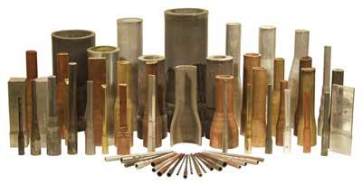
Pointing requirements vary as much as tubular products vary in material and size. While the tube can be of almost any metal, the most common are copper, brass, cupronickel, aluminum, carbon steel, alloy steel, and stainless steel. The basic tube shell is normally hot-produced by an extruding, piercing, or forming and welding process. Other candidates for pointing, regarding tubes made from copper and copper alloys, are intermediate cut-in sizes produced on drawbenches, bull blocks, tube reducers, or continuous drawing machines. These cut-in sizes are normally hard, but in some instances they are annealed.
The Ideal Cross Section
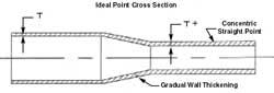
Push pointing a tube without preheating results in perfectly round, concentric ends on thick- or thin-walled tubes, with the point wall thickness being proportionally heavier than the tube wall, as shown in Figure 2. A center hole always remains in the point to permit free passage of air during subsequent processing. A uniform, gradual wall thickening of this conical transition, which is between the tube OD and the point, results in a higher tensile strength in this section of the tube.
Another benefit of push pointing is that while the tube end being reduced is under compression, the metal flows circumferentially. This phenomenon reduces wall thickness variation of the point with respect to the starting tube, which strengthens the point. Because the die produces a perfectly round and concentric point, this point must be just slightly smaller than the draw die through which it must pass.
Furthermore, push pointing results in a high degree of material elongation. This benefit is significant when justifying a pointer to accommodate thick-walled pierced or extruded tubes, whether ferrous or nonferrous.
Push-Pointer Tooling
Push pointers rely on two categories of tooling: pointing dies that size the tube and gripper jaws that hold the tube while the pointing dies advance and retract.
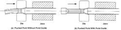
Figure 1. Gripper jaws and a die are not enough (a). The resulting crooked point affects subsequent drawing operations. A patented guide system (b) keeps the end straight.
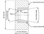
Pointing Dies. In most applications, push-pointing dies are the same type of tool steel or tungsten carbide insert dies used on drawbenches, bull blocks, and continuous drawing machines. However, pointing dies must incorporate several refinements (see Figure 3).
Because a push-pointing die must serve two functions—it must pass onto the tube and it must be withdrawn—the exit side of the die bearing must have a blended relief angle to prevent scraping or cutting the point surface. The intersection between the inlet angle and the bearing should be well-blended to eliminate concentrated pressure at this point, which tends to cause lubrication breakdown, excessive end load on the tube, and scoring of the point surface.
For most ferrous and nonferrous tubes with typical diameter-to-thickness (D/t) ratios, the inlet opening should have a straight, conical contour with an included angle no more than 30 degrees, and preferably less, in the 22- to 24-degree range. To achieve the best pointing results on thick-walled tubes, especially on seamless steel tubes, the angle can be as small as 16 degrees.
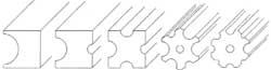
Gripper Jaws. All of the tube gripper jaws are in pairs and consist of two hardened steel halves. Each half can have one to eight semicircular grooves. Each groove is sized to suit a specific nominal tube OD (including normal manufacturing tolerances). The grooved surfaces can be either smooth or rough, depending on the type and condition of the tube and whether or not it is lubricated (see Figure 4).
The length of the jaw and the clamping force required to hold the tube are dictated by the type, condition, and diameter of the tube to be gripped. The force does not have a direct relationship to the rated pushing capacity of the pointer.
Lubrication
In all cases, a lubrication film is necessary between the tube OD and the push-pointing die.
For carbon and alloy steel tubes, batch lubrication on a bundle is common. Nonferrous and stainless steel tubes normally start dry, with a liquid lubricant applied by a recirculating system in the pointer. In the case of bull block drawing of copper tube, enough residual lube usually remains on the tube OD from the previous bench or block draw so that no additional lube is required for push pointing.
In the ferrous industry, lubricating the entire tube before pointing using a phosphate undercoat followed by a reactive soap batch lubricant is the optimal method. This type of coating normally can withstand two or three successive push-pointing die reductions without breakdown.
Pointer Production Requirements
Production requirements vary greatly and depend on the application. In the case of a spinner-type bull block with a carousel system drawing copper tube, the pointer normally must accommodate a new tube size every six to eight coils. However, with an overhead coil handling system, changeovers are less frequent—as few as one every 50 coils.
For long production runs, the pointer may run for days or weeks on the same size. In such applications, it makes sense to integrate the push pointer with the tube handling system. In this scenario, the pointer is required to cycle at the same rate as the primary equipment, which is usually about one tube every 15 to 60 seconds.
In the case of steel tube, push-pointer size changes occur frequently; the work is similar to that performed in a job shop, with up to six size changes per shift. For this reason, it is necessary to use a quick-change system.
About the Authors
About the Publication
subscribe now

The Tube and Pipe Journal became the first magazine dedicated to serving the metal tube and pipe industry in 1990. Today, it remains the only North American publication devoted to this industry, and it has become the most trusted source of information for tube and pipe professionals.
start your free subscription- Stay connected from anywhere

Easily access valuable industry resources now with full access to the digital edition of The Fabricator.

Easily access valuable industry resources now with full access to the digital edition of The Welder.

Easily access valuable industry resources now with full access to the digital edition of The Tube and Pipe Journal.

Easily access valuable industry resources now with full access to the digital edition of The Fabricator en Español.
- Podcasting

In this episode of The Fabricator Podcast, Caleb Chamberlain, co-founder and CEO of OSH Cut, discusses his company’s...
- Trending Articles
1
Team Industries names director of advanced technology and manufacturing

2
Orbital tube welding webinar to be held April 23

3
Chain hoist offers 60-ft. remote control range

4
Push-feeding saw station cuts nonferrous metals

5
Corrosion-inhibiting coating can be peeled off after use
